144
8025I–AVR–02/09
ATmega48P/88P/168P/328P
15. 8-bit Timer/Counter2 with PWM and Asynchronous Operation
15.1 Features
• Single Channel Counter
• Clear Timer on Compare Match (Auto Reload)
• Glitch-free, Phase Correct Pulse Width Modulator (PWM)
• Frequency Generator
• 10-bit Clock Prescaler
• Overflow and Compare Match Interrupt Sources (TOV2, OCF2A and OCF2B)
• Allows Clocking from External 32 kHz Watch Crystal Independent of the I/O Clock
15.2 Overview
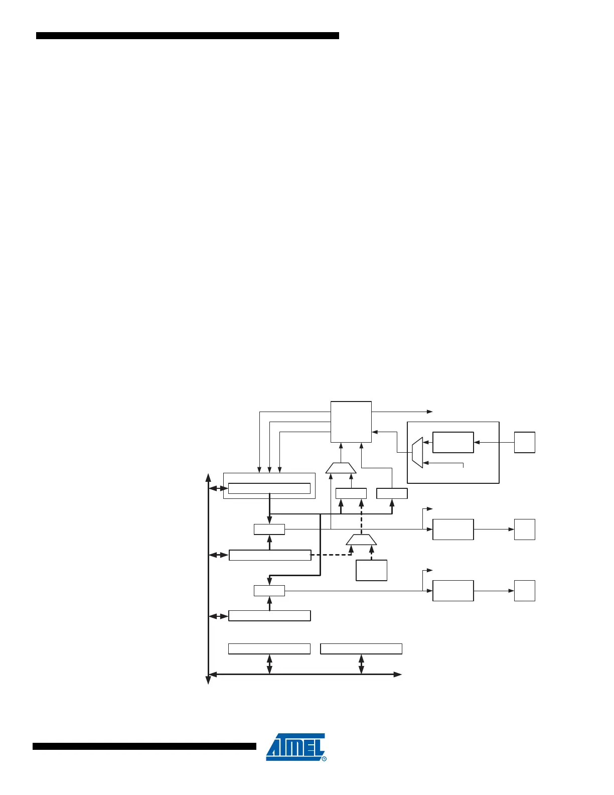
Timer/Counter2 is a general purpose, single channel, 8-bit Timer/Counter module. A simplified
block diagram of the 8-bit Timer/Counter is shown in Figure 15-1. For the actual placement of
I/O pins, refer to ”Pinout ATmega48P/88P/168P/328P” on page 2. CPU accessible I/O Regis-
ters, including I/O bits and I/O pins, are shown in bold. The device-specific I/O Register and bit
locations are listed in the ”Register Description” on page 158.
The PRTIM2 bit in ”Minimizing Power Consumption” on page 42 must be written to zero to
enable Timer/Counter2 module.
Figure 15-1. 8-bit Timer/Counter Block Diagram
Clock Select
Timer/Counter
DATA BUS
OCRnA
OCRnB
=
=
TCNTn
Waveform
Generation
Waveform
Generation
OCnA
OCnB
=
Fixed
TOP
Value
Control Logic
=
0
TOP BOTTOM
Count
Clear
Direction
TOVn
(Int.Req.)
OCnA
(Int.Req.)
OCnB
(Int.Req.)
TCCRnA TCCRnB
Tn
Edge
Detector
( From Prescaler )
clk
Tn