267
8025I–AVR–02/09
ATmega48P/88P/168P/328P
22. debugWIRE On-chip Debug System
22.1 Features
• Complete Program Flow Control
• Emulates All On-chip Functions, Both Digital and Analog, except RESET Pin
• Real-time Operation
• Symbolic Debugging Support (Both at C and Assembler Source Level, or for Other HLLs)
• Unlimited Number of Program Break Points (Using Software Break Points)
• Non-intrusive Operation
• Electrical Characteristics Identical to Real Device
• Automatic Configuration System
• High-Speed Operation
• Programming of Non-volatile Memories
22.2 Overview
The debugWIRE On-chip debug system uses a One-wire, bi-directional interface to control the
program flow, execute AVR instructions in the CPU and to program the different non-volatile
memories.
22.3 Physical Interface
When the debugWIRE Enable (DWEN) Fuse is programmed and Lock bits are unprogrammed,
the debugWIRE system within the target device is activated. The RESET port pin is configured
as a wire-AND (open-drain) bi-directional I/O pin with pull-up enabled and becomes the commu-
nication gateway between target and emulator.
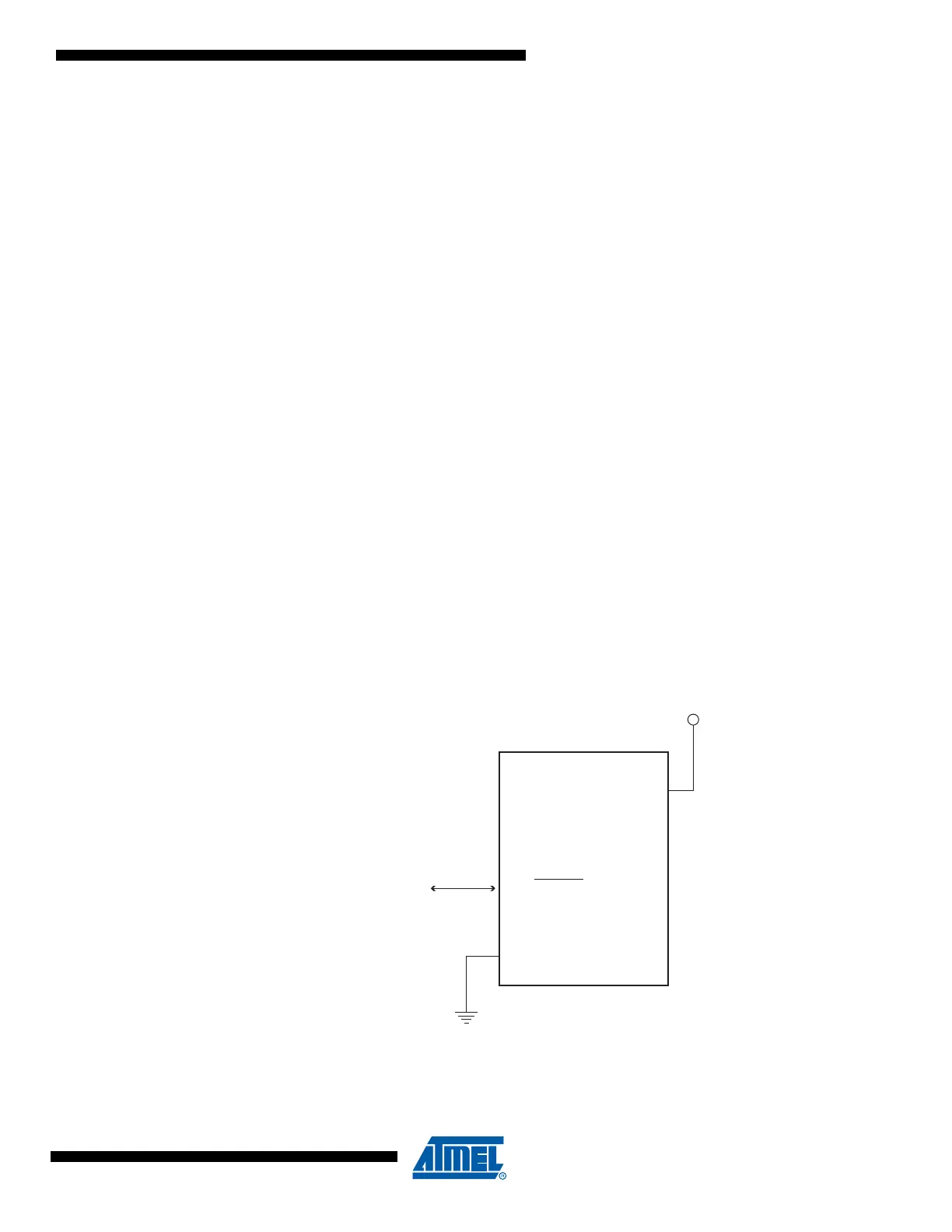
Figure 22-1. The debugWIRE Setup
Figure 22-1 shows the schematic of a target MCU, with debugWIRE enabled, and the emulator
connector. The system clock is not affected by debugWIRE and will always be the clock source
selected by the CKSEL Fuses.
dW
GND
dW(RESET)
VCC
1.8 - 5.5V