34
8025I–AVR–02/09
ATmega48P/88P/168P/328P
Note: 1. Note that the 128 kHz oscillator is a very low power clock source, and is not designed for a
high accuracy.
When this clock source is selected, start-up times are determined by the SUT Fuses as shown in
Table 6-13.
Note: 1. If the RSTDISBL fuse is programmed, this start-up time will be increased to
14CK + 4.1 ms to ensure programming mode can be entered.
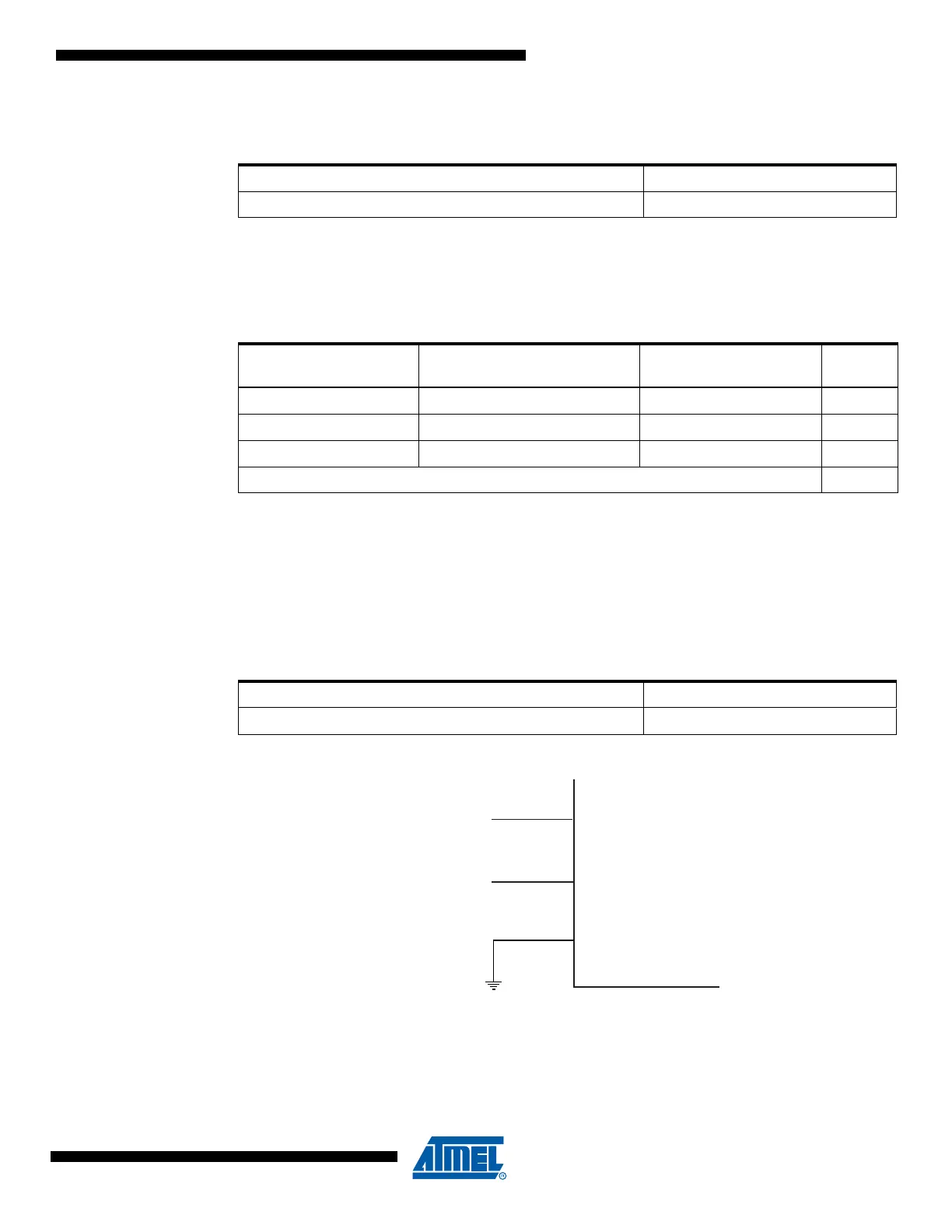
6.8 External Clock
To drive the device from an external clock source, XTAL1 should be driven as shown in Figure
6-4 on page 34. To run the device on an external clock, the CKSEL Fuses must be programmed
to “0000” (see Table 6-14).
Figure 6-4. External Clock Drive Configuration
When this clock source is selected, start-up times are determined by the SUT Fuses as shown in
Table 6-15.
Table 6-12. 128 kHz Internal Oscillator Operating Modes
Nominal Frequency
(1)
CKSEL3..0
128 kHz 0011
Table 6-13. Start-up Times for the 128 kHz Internal Oscillator
Power Conditions
Start-up Time from Power-
down and Power-save
Additional Delay from
Reset SUT1..0
BOD enabled 6 CK 14CK
(1)
00
Fast rising power 6 CK 14CK + 4 ms 01
Slowly rising power 6 CK 14CK + 64 ms 10
Reserved 11
Table 6-14. Crystal Oscillator Clock Frequency
Frequency CKSEL3..0
0 - 20 MHz 0000
NC
EXTERNAL
CLOCK
SIGNAL
XTAL2
XTAL1
GND