298
8025I–AVR–02/09
ATmega48P/88P/168P/328P
2. The SPIEN Fuse is not accessible in serial programming mode.
3. See ”WDTCSR – Watchdog Timer Control Register” on page 54 for details.
4. The default value of BOOTSZ[1:0] results in maximum Boot Size. See ”Pin Name Mapping” on
page 300.
Note: 1. The default value of SUT1..0 results in maximum start-up time for the default clock source.
See Table 6-11 on page 33 for details.
2. The default setting of CKSEL3..0 results in internal RC Oscillator @ 8 MHz. See Table 6-10 on
page 33 for details.
3. The CKOUT Fuse allows the system clock to be output on PORTB0. See ”Clock Output Buffer”
on page 35 for details.
4. See ”System Clock Prescaler” on page 35 for details.
The status of the Fuse bits is not affected by Chip Erase. Note that the Fuse bits are locked if
Lock bit1 (LB1) is programmed. Program the Fuse bits before programming the Lock bits.
25.2.1 Latching of Fuses
The fuse values are latched when the device enters programming mode and changes of the
fuse values will have no effect until the part leaves Programming mode. This does not apply to
the EESAVE Fuse which will take effect once it is programmed. The fuses are also latched on
Power-up in Normal mode.
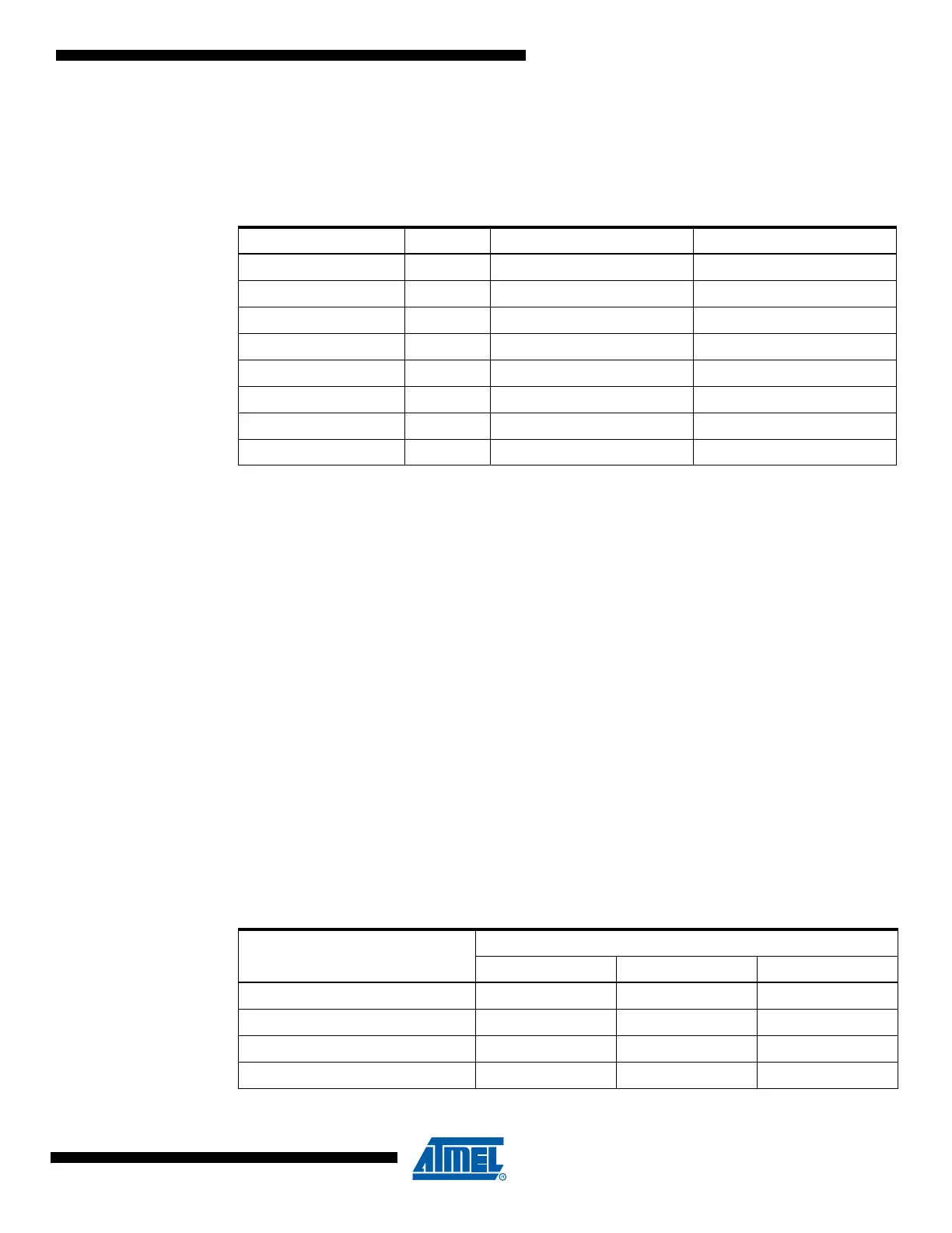
25.3 Signature Bytes
All Atmel microcontrollers have a three-byte signature code which identifies the device. This
code can be read in both serial and parallel mode, also when the device is locked. The three
bytes reside in a separate address space. For the ATmega48P/88P/168P/328P the signature
bytes are given in Table 25-10.
Table 25-9. Fuse Low Byte
Low Fuse Byte Bit No Description Default Value
CKDIV8
(4)
7 Divide clock by 8 0 (programmed)
CKOUT
(3)
6 Clock output 1 (unprogrammed)
SUT1 5 Select start-up time 1 (unprogrammed)
(1)
SUT0 4 Select start-up time 0 (programmed)
(1)
CKSEL3 3 Select Clock source 0 (programmed)
(2)
CKSEL2 2 Select Clock source 0 (programmed)
(2)
CKSEL1 1 Select Clock source 1 (unprogrammed)
(2)
CKSEL0 0 Select Clock source 0 (programmed)
(2)
Table 25-10. Device ID
Part
Signature Bytes Address
0x000 0x001 0x002
ATmega48P 0x1E 0x92 0x0A
ATmega88P 0x1E 0x93 0x0F
ATmega168P 0x1E 0x94 0x0B
ATmega328P 0x1E 0x95 0x0F