254
8025I–AVR–02/09
ATmega48P/88P/168P/328P
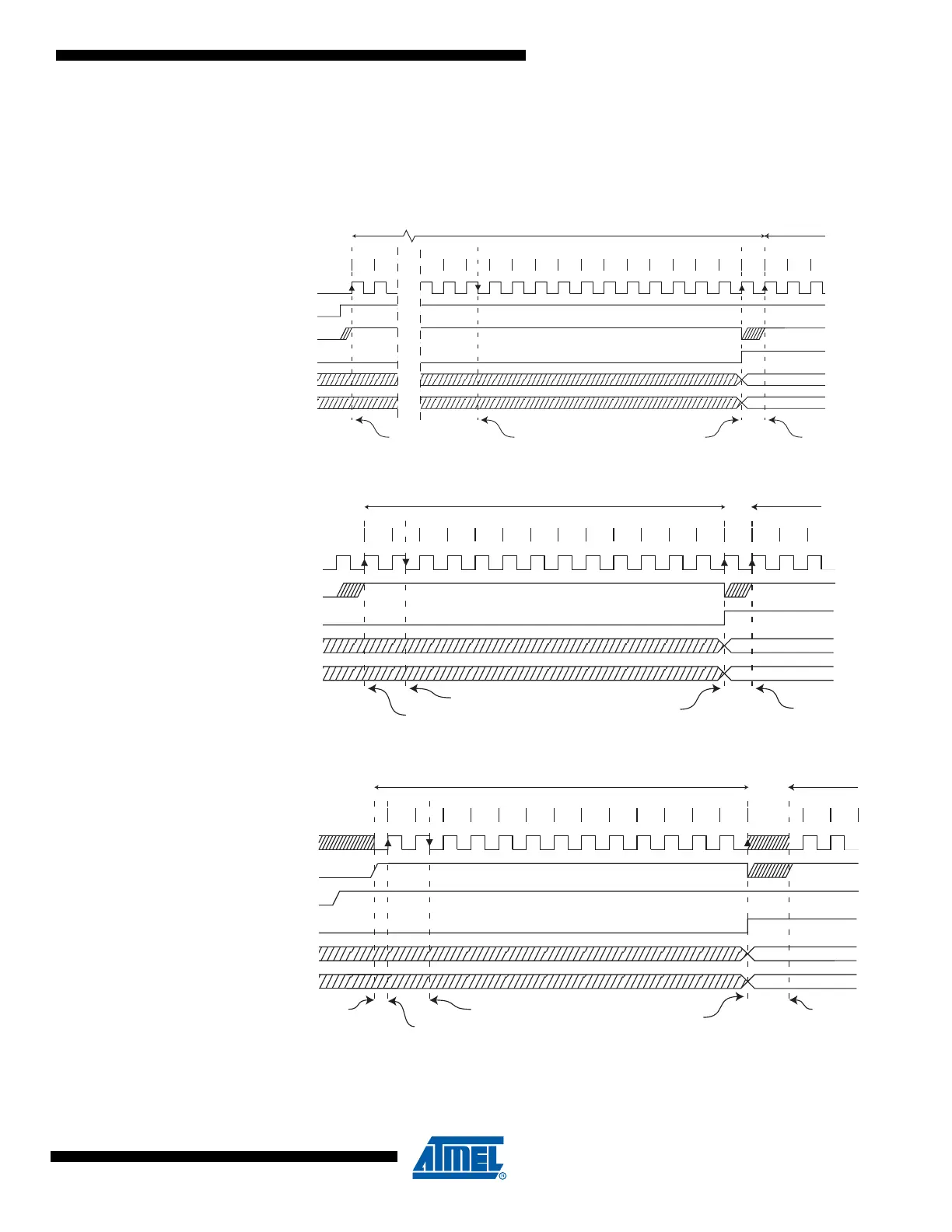
In Free Running mode, a new conversion will be started immediately after the conversion com-
pletes, while ADSC remains high. For a summary of conversion times, see Table 21-1 on page
255.
Figure 21-4. ADC Timing Diagram, First Conversion (Single Conversion Mode)
Figure 21-5. ADC Timing Diagram, Single Conversion
Figure 21-6. ADC Timing Diagram, Auto Triggered Conversion
Sign and MSB of Result
LSB of Result
ADC Clock
ADSC
Sample & Hold
ADIF
ADCH
ADCL
Cycle Number
ADEN
1 212
13
14 15
16 17
18 19 20 21 22 23
24 25
1 2
First Conversion
Next
Conversion
3
MUX and REFS
Update
MUX and REFS
Update
Conversion
Complete
1
2 3 4 5 6 7 8
9 10 11 12 13
Sign and MSB of Result
LSB of Result
ADC Clock
ADSC
ADIF
ADCH
ADCL
Cycle Number
12
One Conversion Next Conversion
3
Sample & Hold
MUX and REFS
Update
Conversion
Complete
MUX and REFS
Update
1 2 3 4 5 6 7 8
9
10 11 12 13
Sign and MSB of Result
LSB of Result
ADC Clock
Trigger
Source
ADIF
ADCH
ADCL
Cycle Number
12
One Conversion Next Conversion
Conversion
Complete
Prescaler
Reset
ADATE
Prescaler
Reset
Sample &
Hold
MUX and REFS
Update