31
8025I–AVR–02/09
ATmega48P/88P/168P/328P
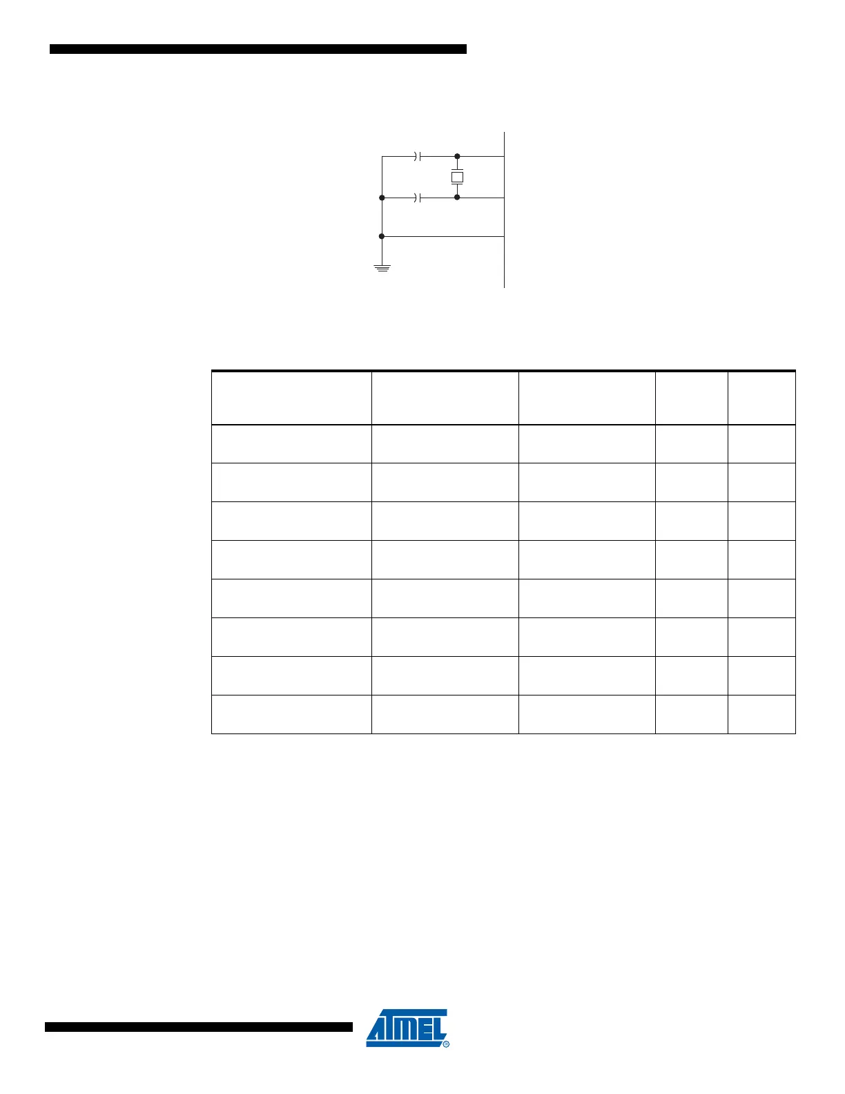
Figure 6-3. Crystal Oscillator Connections
Notes: 1. These options should only be used when not operating close to the maximum frequency of the
device, and only if frequency stability at start-up is not important for the application. These
options are not suitable for crystals.
2. These options are intended for use with ceramic resonators and will ensure frequency stability
at start-up. They can also be used with crystals when not operating close to the maximum fre-
quency of the device, and if frequency stability at start-up is not important for the application.
Table 6-6. Start-up Times for the Full Swing Crystal Oscillator Clock Selection
Oscillator Source /
Power Conditions
Start-up Time from
Power-down and
Power-save
Additional Delay
from Reset
(V
CC
= 5.0V) CKSEL0 SUT1..0
Ceramic resonator, fast
rising power
258 CK 14CK + 4.1 ms
(1)
000
Ceramic resonator, slowly
rising power
258 CK 14CK + 65 ms
(1)
001
Ceramic resonator, BOD
enabled
1K CK 14CK
(2)
010
Ceramic resonator, fast
rising power
1K CK 14CK + 4.1 ms
(2)
011
Ceramic resonator, slowly
rising power
1K CK 14CK + 65 ms
(2)
100
Crystal Oscillator, BOD
enabled
16K CK 14CK 1 01
Crystal Oscillator, fast
rising power
16K CK 14CK + 4.1 ms 1 10
Crystal Oscillator, slowly
rising power
16K CK 14CK + 65 ms 1 11
XTAL2 (TOSC2)
XTAL1 (TOSC1)
GND
C2
C1