36
7598H–AVR–07/09
ATtiny25/45/85
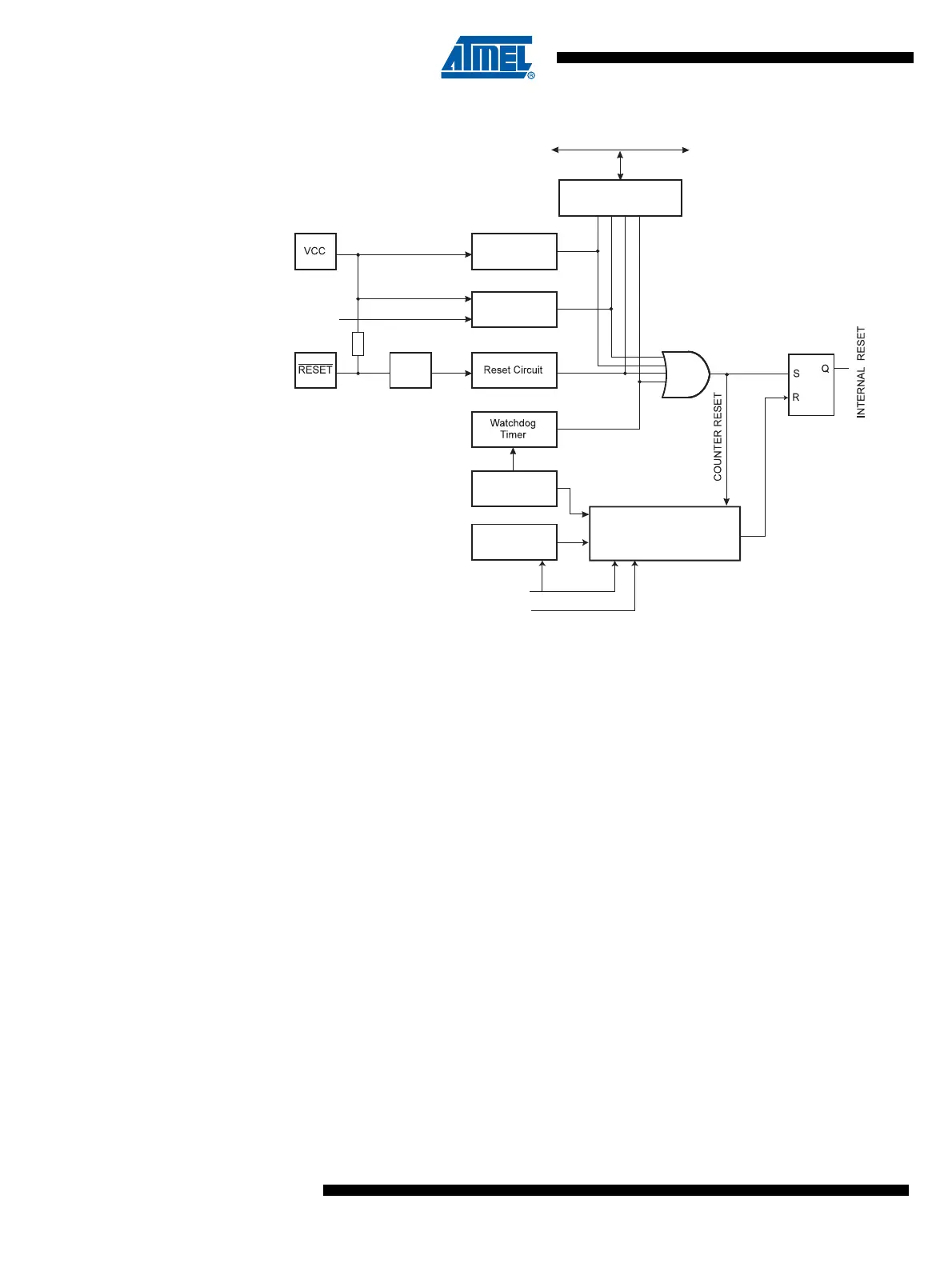
Figure 8-1. Reset Logic
8.3 Power-on Reset
A Power-on Reset (POR) pulse is generated by an On-chip detection circuit. The detection level
is defined in Table 8-1. The POR is activated whenever V
CC
is below the detection level. The
POR circuit can be used to trigger the Start-up Reset, as well as to detect a failure in supply
voltage.
A Power-on Reset (POR) circuit ensures that the device is reset from Power-on. Reaching the
Power-on Reset threshold voltage invokes the delay counter, which determines how long the
device is kept in RESET after V
CC
rise. The RESET signal is activated again, without any delay,
when V
CC
decreases below the detection level.
MCU Status
Register (MCUSR)
Brown-out
Reset Circuit
BODLEVEL [1..0]
Delay Counters
CKSEL[1:0]
CK
TIMEOUT
WDRF
BORF
EXTRF
PORF
DATA BUS
Clock
Generator
SPIKE
FILTER
Pull-up Resistor
Watchdog
Oscillator
SUT
1:0
Power-on Reset
Circuit