37
7598H–AVR–07/09
ATtiny25/45/85
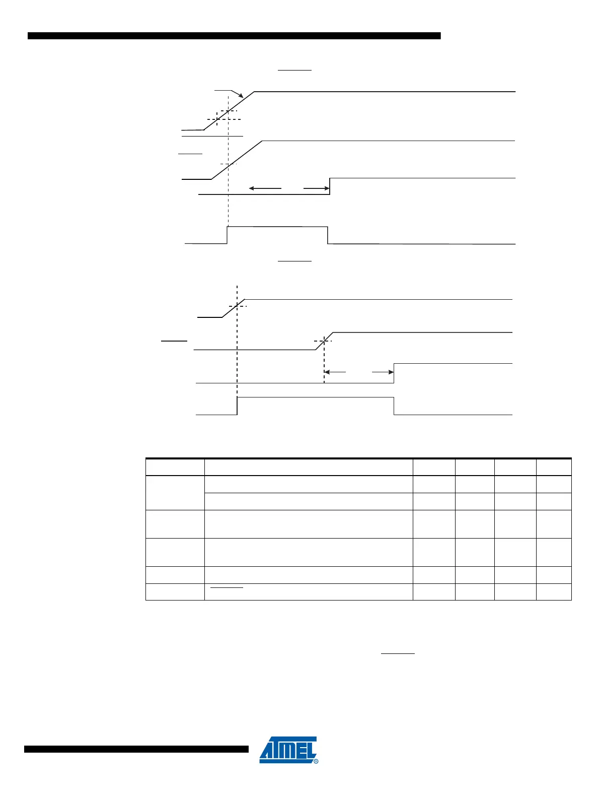
Figure 8-2. MCU Start-up, RESET Tied to V
CC
Figure 8-3. MCU Start-up, RESET Extended Externally
Table 8-1. Power On Reset Specifications
Note: 1. Before rising the supply has to be between V
PORMIN
and V
PORMAX
to ensure Reset.
8.4 External Reset
An External Reset is generated by a low level on the RESET pin if enabled. Reset pulses longer
than the minimum pulse width (see Table 8-1) will generate a reset, even if the clock is not run-
ning. Shorter pulses are not guaranteed to generate a reset. When the applied signal reaches
the Reset Threshold Voltage – V
RST
– on its positive edge, the delay counter starts the MCU
after the Time-out period – t
TOUT
–
has expired.
Symbol Parameter Min Typ Max Units
V
POT
Power-on Reset Threshold Voltage (rising) 1.1 1.4 1.7 V
Power-on Reset Threshold Voltage (falling)
(1)
0.8 1.3 1.6 V
V
PORMAX
VCC Max. start voltage to ensure internal
Power-on Reset signal
0.4 V
V
PORMIN
VCC Min. start voltage to ensure internal
Power-on Reset signal
-0.1 V
V
CCRR
VCC Rise Rate to ensure Power-on Reset 0.01 V/ms
V
RST
RESET Pin Threshold Voltage 0.1 V
CC
0.9V
CC
V
RESET
TIME-OUT
INTERNAL
RESET
t
TOUT
V
RST
V
PORMAX
V
CC
CCRR
V
V
PORMIN
RESET
TIME-OUT
INTERNAL
RESET
t
TOU T
V
RST
V
CC