38
7598H–AVR–07/09
ATtiny25/45/85
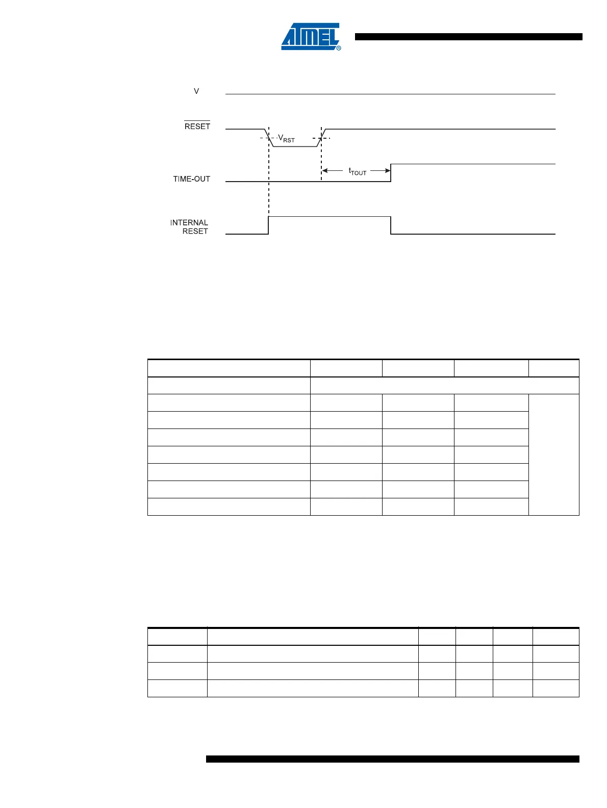
Figure 8-4. External Reset During Operation
8.5 Brown-out Detection
ATtiny25/45/85 has an On-chip Brown-out Detection (BOD) circuit for monitoring the V
CC
level
during operation by comparing it to a fixed trigger level. The trigger level for the BOD can be
selected by the BODLEVEL Fuses. The trigger level has a hysteresis to ensure spike free
Brown-out Detection. The hysteresis on the detection level should be interpreted as V
BOT+
=
V
BOT
+ V
HYST
/2 and V
BOT-
= V
BOT
- V
HYST
/2.
Note: 1. V
BOT
may be below nominal minimum operating voltage for some devices. For devices where
this is the case, the device is tested down to V
CC
= V
BOT
during the production test. This guar-
antees that a Brown-out Reset will occur before V
CC
drops to a voltage where correct
operation of the microcontroller is no longer guaranteed.
2. Centered value, not tested.
Notes: 1. This is the limit to which VDD can be lowered without losing RAM data
Table 8-2. BODLEVEL Fuse Coding
(1)
BODLEVEL [2..0] Fuses Min V
BOT
Typ V
BOT
Max V
BOT
Units
111 BOD Disabled
110 1.7 1.8 2.0
V
101 2.5 2.7 2.9
100 4.0 4.3 4.6
011 2.3
(2)
010 2.2
(2)
001 1.9
(2)
000 2.0
(2)
Table 8-3. Brown-out Characteristics
Symbol Parameter Min Typ Max Units
V
RAM
RAM Retention Voltage
(1)
50 mV
V
HYST
Brown-out Detector Hysteresis 50 mV
t
BOD
Min Pulse Width on Brown-out Reset 2 µs