82
7598H–AVR–07/09
ATtiny25/45/85
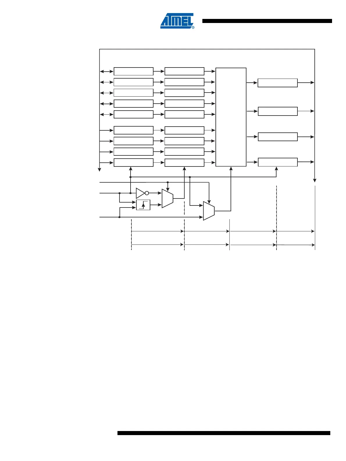
Figure 14-2. Timer/Counter 1 Synchronization Register Block Diagram.
Timer/Counter1 and the prescaler allow running the CPU from any clock source while the pres-
caler is operating on the fast 64 MHz (or 32 MHz in Low Speed Mode) PCK clock in the
asynchronous mode.
Note that the system clock frequency must be lower than one third of the PCK frequency. The
synchronization mechanism of the asynchronous Timer/Counter1 needs at least two edges of
the PCK when the system clock is high. If the frequency of the system clock is too high, it is a
risk that data or control values are lost.
The following Figure 14-3 shows the block diagram for Timer/Counter1.
8-BIT DATABUS
OCR1A OCR1A_SI
TCNT_SO
OCR1B OCR1B_SI
OCR1C OCR1C_SI
TCCR1 TCCR1_SI
GTCCR GTCCR_SI
TCNT1 TCNT1_SI
OCF1A OCF1A_SI
OCF1B OCF1B_SI
TOV1 TOV1_SI
TOV1_SO
OCF1B_SO
OCF1A_SO
TCNT1
S
A
S
A
PCKE
CK
PCK
IO-registers Input synchronization
registers
Timer/Counter1 Output synchronization
registers
SYNC
MODE
ASYNC
MODE
1 CK Delay 1/2 CK Delay
1 - 2 PCK Delay 1 PCK Delay ~1 CK Delay No Delay
TCNT1
OCF1A
OCF1B
TOV1
1/2 CK Delay 1 CK Delay