61
7679H–CAN–08/08
AT90CAN32/64/128
Notes: 1. When the IVSEL bit in MCUCR is set, Interrupt Vectors will be moved to the start of the Boot
Flash Section. The address of each Interrupt Vector will then be the address in this table
added to the start address of the Boot Flash Section.
2. When the BOOTRST Fuse is programmed, the device will jump to the Boot Loader address at
reset, see “Boot Loader Support – Read-While-Write Self-Programming” on page 321.
Table 8-2 shows reset and Interrupt Vectors placement for the various combinations of
BOOTRST and IVSEL settings. If the program never enables an interrupt source, the Interrupt
Vectors are not used, and regular program code can be placed at these locations. This is also
the case if the Reset Vector is in the Application section while the Interrupt Vectors are in the
Boot section or vice versa.
Note: 1. The Boot Reset Address is shown in Table 24-6 on page 334. For the BOOTRST Fuse “1”
means unprogrammed while “0” means programmed.
The most typical and general program setup for the Reset and Interrupt Vector Addresses in
AT90CAN32/64/128 is:
;Address Labels Code Comments
0x0000 jmp RESET ; Reset Handler
0x0002 jmp EXT_INT0 ; IRQ0 Handler
0x0004 jmp EXT_INT1 ; IRQ1 Handler
0x0006 jmp EXT_INT2 ; IRQ2 Handler
0x0008 jmp EXT_INT3 ; IRQ3 Handler
0x000A jmp EXT_INT4 ; IRQ4 Handler
0x000C jmp EXT_INT5 ; IRQ5 Handler
0x000E jmp EXT_INT6 ; IRQ6 Handler
0x0010 jmp EXT_INT7 ; IRQ7 Handler
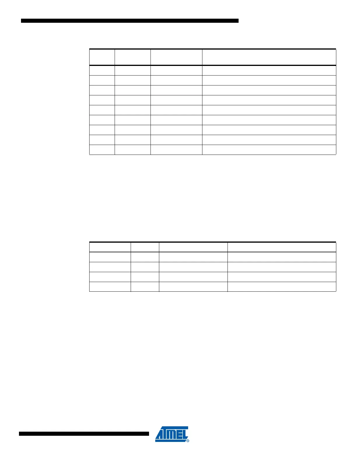
29 0x0038 TIMER3 COMPA Timer/Counter3 Compare Match A
30 0x003A TIMER3 COMPB Timer/Counter3 Compare Match B
31 0x003C TIMER3 COMPC Timer/Counter3 Compare Match C
32 0x003E TIMER3 OVF Timer/Counter3 Overflow
33 0x0040 USART1, RX USART1, Rx Complete
34 0x0042 USART1, UDRE USART1 Data Register Empty
35 0x0044 USART1, TX USART1, Tx Complete
36 0x0046 TWI Two-wire Serial Interface
37 0x0048 SPM READY Store Program Memory Ready
Table 8-2. Reset and Interrupt Vectors Placement
(1)
BOOTRST IVSEL Reset Address Interrupt Vectors Start Address
1 0 0x0000 0x0002
1 1 0x0000 Boot Reset Address + 0x0002
0 0 Boot Reset Address 0x0002
0 1 Boot Reset Address Boot Reset Address + 0x0002
Table 8-1. Reset and Interrupt Vectors (Continued)
Vector
No.
Program
Address
(1)
Source Interrupt Definition

 Loading...


