74
7679H–CAN–08/08
AT90CAN32/64/128
• Bit 4 – PUD: Pull-up Disable
When this bit is written to one, the pull-ups in the I/O ports are disabled even if the DDxn and
PORTxn Registers are configured to enable the pull-ups ({DDxn, PORTxn} = 0b01). See “Con-
figuring the Pin” for more details about this feature.
9.3.2 Alternate Functions of Port A
The Port A has an alternate function as the address low byte and data lines for the External
Memory Interface.
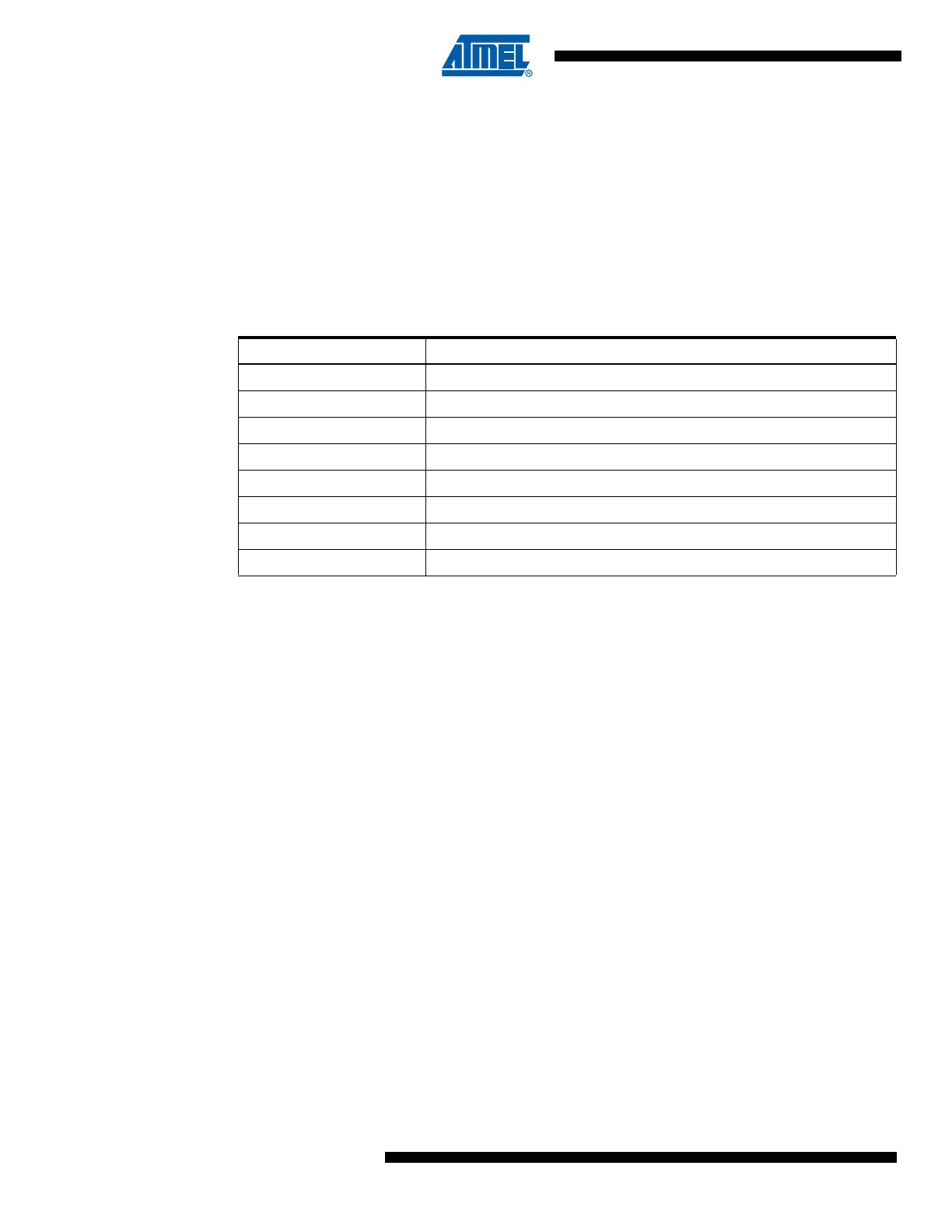
The Port A pins with alternate functions are shown in Table 9-3.
The alternate pin configuration is as follows:
• AD7 – Port A, Bit 7
AD7, External memory interface address 7 and Data 7.
• AD6 – Port A, Bit 6
AD6, External memory interface address 6 and Data 6.
• AD5 – Port A, Bit 5
AD5, External memory interface address 5 and Data 5.
• AD4 – Port A, Bit 4
AD4, External memory interface address 4 and Data 4.
• AD3 – Port A, Bit 3
AD3, External memory interface address 3 and Data 3.
• AD2 – Port A, Bit 2
AD2, External memory interface address 2 and Data 2.
• AD1 – Port A, Bit 1
AD1, External memory interface address 1 and Data 1.
• AD0 – Port A, Bit 0
AD0, External memory interface address 0 and Data 0.
Table 9-3. Port A Pins Alternate Functions
Port Pin Alternate Function
PA7 AD7 (External memory interface address and data bit 7)
PA6 AD6 (External memory interface address and data bit 6)
PA5 AD5 (External memory interface address and data bit 5)
PA4 AD4 (External memory interface address and data bit 4)
PA3 AD3 (External memory interface address and data bit 3)
PA2 AD2 (External memory interface address and data bit 2)
PA1 AD1 (External memory interface address and data bit 1)
PA0 AD0 (External memory interface address and data bit 0)

 Loading...


