30
AT90S2313
0839G–08/01
The Stop condition provides a Timer Enable/Disable function. The CK down divided
modes are scaled directly from the CK oscillator clock. If the external pin modes are
used for Timer/Counter0, transitions on PD4/(T0) will clock the counter even if the pin is
configured as an output. This feature can give the user software control of the counting.
Timer/Counter0 – TCNT0
The Timer/Counter0 is realized as an up-counter with read and write access. If the
Timer/Counter0 is written and a clock source is present, the Timer/Counter0 continues
counting in the timer clock cycle following the write operation.
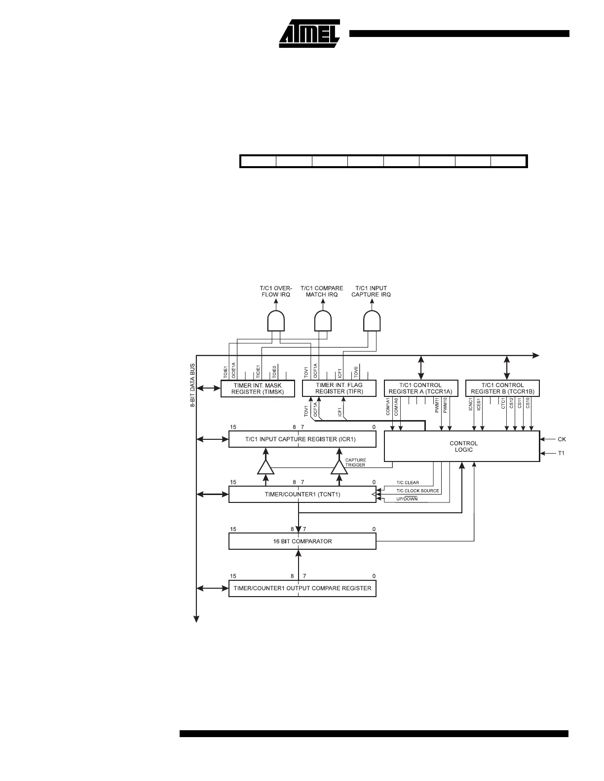
16-bit Timer/Counter1 Figure 30 shows the block diagram for Timer/Counter1.
Figure 30. Timer/Counter1 Block Diagram
The 16-bit Timer/Counter1 can select clock source from CK, prescaled CK or an external
pin. In addition, it can be stopped as described in the specification for the Timer/Counter1
Control Register (TCCR1B). The different status flags (Overflow, Compare Match and
Capture Event) and control signals are found in the Timer/Counter Interrupt Flag Register
(TIFR). The interrupt enable/disable settings for Timer/Counter1 are found in the Tim-
er/Counter Interrupt Mask Register (TIMSK).
Bit 76543210
$32 ($52) MSB LSB TCNT0
Read/Write R/W R/W R/W R/W R/W R/W R/W R/W
Initial value00000000
T1

 Loading...


