62
AT90S2313
0839G–08/01
Memory Programming
Program and Data
Memory Lock Bits
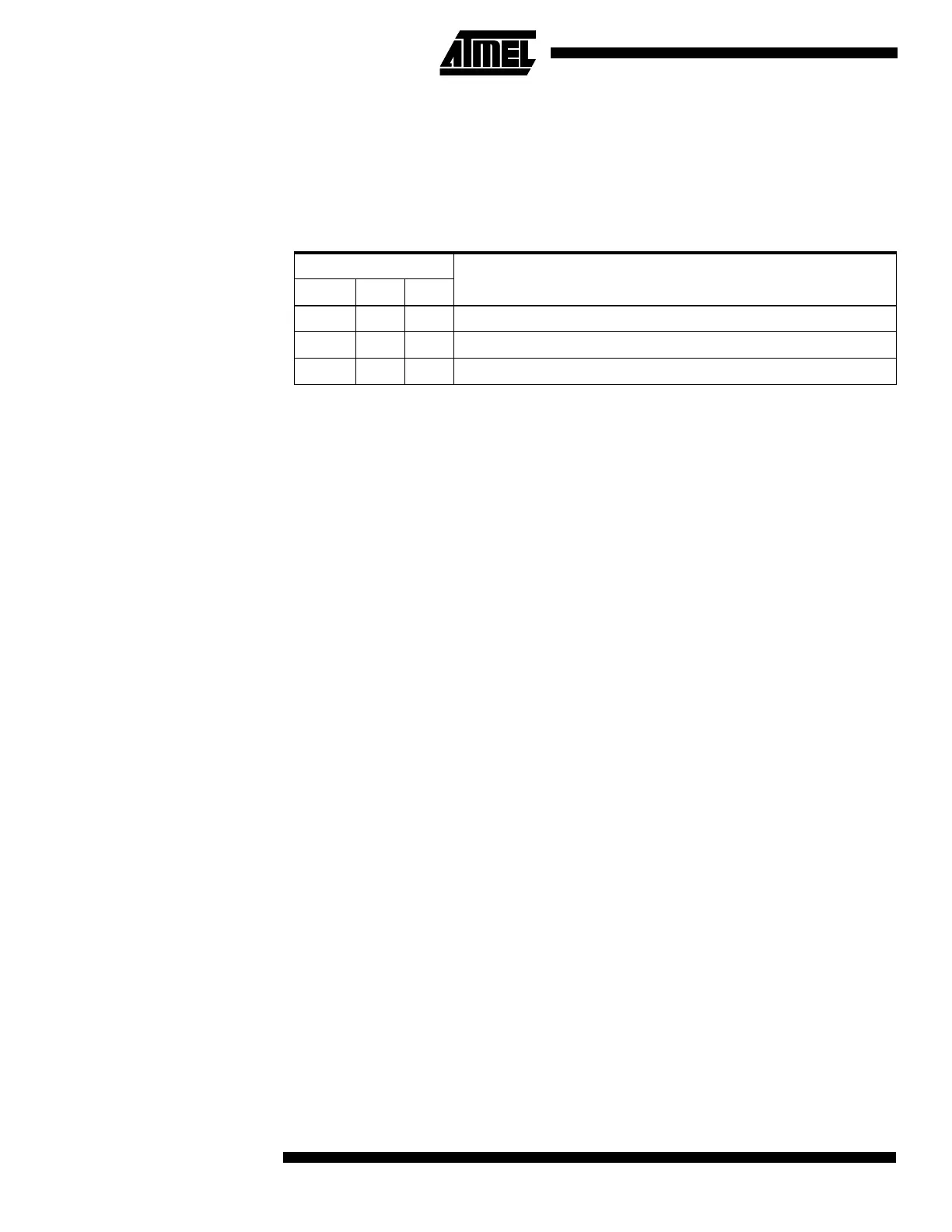
The AT90S2313 MCU provides two Lock bits that can be left unprogrammed (“1”) or can
be programmed (“0”) to obtain the additional features listed in Table 21. The Lock bits
can only be erased with the Chip Erase operation.
Note: 1. In the Parallel mode, further programming of the Fuse bits are also disabled. Pro-
gram the Fuse bits before programming the Lock bits.
Fuse Bits The AT90S2313 has two Fuse bits: SPIEN and FSTRT.
• When the SPIEN Fuse is programmed (“0”), Serial Program and Data Downloading
is enabled. The default value is programmed (“0”).
• When the FSTRT Fuse is programmed (“0”), the short start-up time is selected. The
default value is unprogrammed (“1”). Parts with this bit pre-programmed (“0”) can be
delivered on demand.
The Fuse bits are not accessible in Serial Programming Mode. The status of the Fuses
are not affected by Chip Erase.
Signature Bytes All Atmel microcontrollers have a 3-byte signature code that identifies the device. This
code can be read in both serial and parallel mode. The three bytes reside in a separate
address space.
For the AT90S2313
(1)
they are:
1. $000: $1E (indicates manufactured by Atmel)
2. $001: $91 (indicates 2 Kb Flash memory)
3. $002: $01 (indicates AT90S2313 device when signature byte $001 is $91)
Note: 1. When both Lock bits are programmed (Lock mode 3), the signature bytes cannot be
read in serial mode. Reading the signature bytes will return: $00, $01 and $02.
Programming the Flash
and EEPROM
Atmel’s AT90S2313 offers 2K bytes of in-system reprogrammable Flash program mem-
ory and 128 bytes of EEPROM data memory.
The AT90S2313 is shipped with the on-chip Flash program and EEPROM data memory
arrays in the erased state (i.e., contents = $FF) and ready to be programmed. This
device supports a high-voltage (12V) Parallel Programming Mode and a low-voltage
Serial Programming Mode. The +12V is used for programming enable only, and no cur-
rent of significance is drawn by this pin. The Serial Programming Mode provides a
convenient way to download program and data into the AT90S2313 inside the user’s
system.
The program and EEPROM memory arrays in the AT90S2313 are programmed byte-
by-byte in either programming mode. For the EEPROM, an auto-erase cycle is provided
within the self-timed write instruction in the Serial Programming Mode. During program-
ming, the supply voltage must be in accordance with Table 22.
Table 21. Lock Bit Protection Modes
Memory Lock Bits
Protection TypeMode LB1 LB2
1 1 1 No memory lock features enabled.
2 0 1 Further programming of the Flash and EEPROM is disabled.
(1)
3 0 0 Same as mode 2, and verify is also disabled.

 Loading...


