EasyManuals Logo

Atmel AVR AT90S2313 User Manual

Atmel AVR AT90S2313
91 pages
To Next Page IconTo Next Page
To Previous Page IconTo Previous Page
Page #81 background image
81
AT90S2313
0839G–08/01
Note: Sink and source capabilities of I/O ports are measured on one pin at a time.
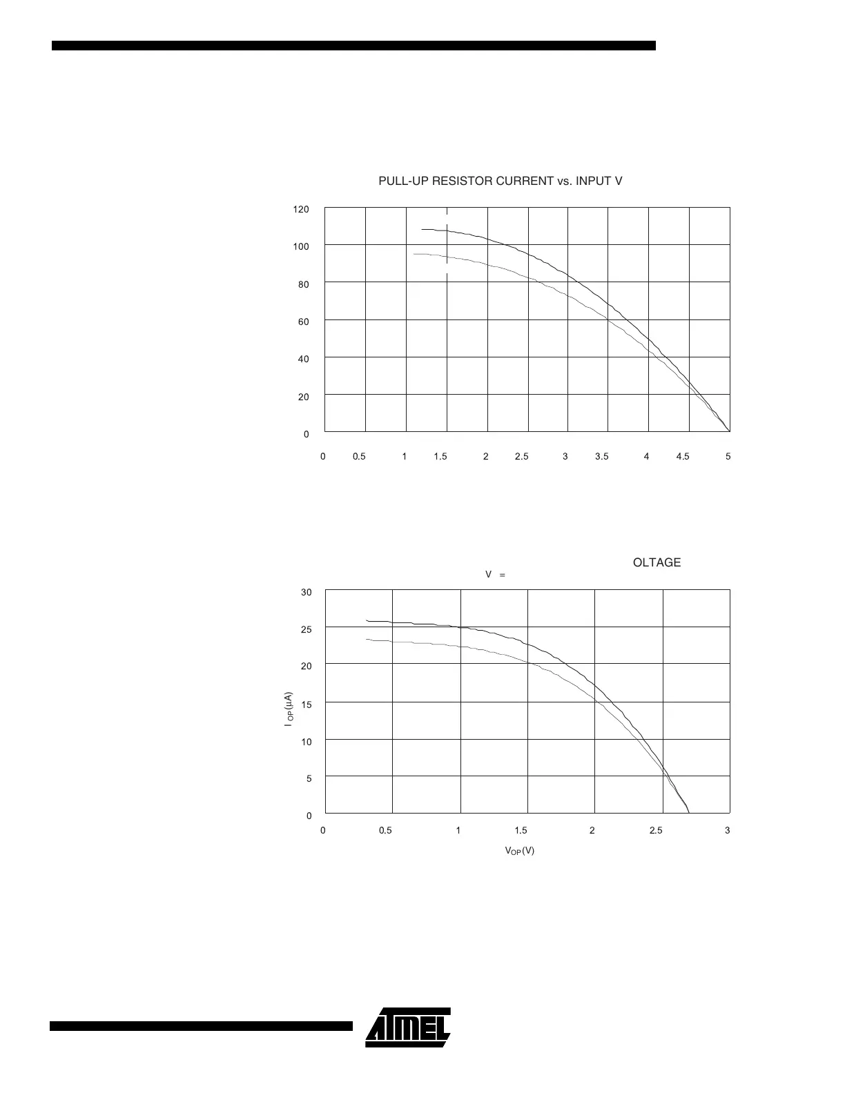
Figure 68. Pull-up Resistor Current vs. Input Voltage
Figure 69. Pull-up Resistor Current vs. Input Voltage
0
20
40
60
80
100
120
0 0.5 1 1.5 2 2.5 3 3.5 4 4.5 5
PULL-UP RESISTOR CURRENT vs. INPUT VOLTAGE
V = 5V
cc
I (µA)
OP
V (V)
OP
T = 85˚C
A
T = 25˚C
A
0
5
10
15
20
25
30
0 0.5 1 1.5 2 2.5 3
PULL-UP RESISTOR CURRENT vs. INPUT VOLTAGE
I (µA)
OP
V (V)
OP
V = 2.7V
cc
T = 85˚C
A
T = 25˚C
A

Table of Contents

Questions and Answers:

Question and Answer IconNeed help?

Do you have a question about the Atmel AVR AT90S2313 and is the answer not in the manual?

Atmel AVR AT90S2313 Specifications

General IconGeneral
ArchitectureAVR
CPU8-bit
ManufacturerAtmel
ModelAT90S2313
Flash Memory2 KB
SRAM128 Bytes
EEPROM128 Bytes
Clock SpeedUp to 10 MHz
I/O Pins15
Timer1 x 8-bit, 1 x 16-bit
Operating Temperature Range-40°C to +85°C
Data Bus Width8-bit
Communication InterfacesUSART
PackageSOIC
SeriesAVR AT90S

Related product manuals