INSTALLATION
22 | MVE User Manual (710-17074-00G)
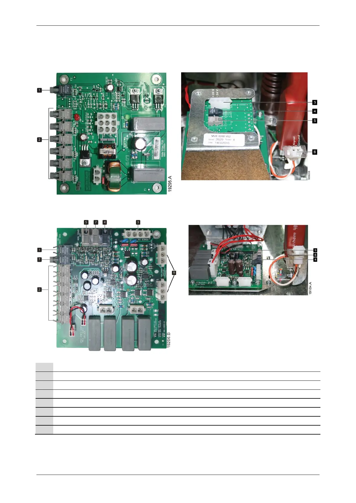
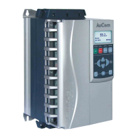
6.11 Terminations for Adapter Board and Gate Drive Board
• MVE-0070~0540, V02~V06
Gate drive board - Layout view
Adapter board - Installed view
• MVE-0070~0540, V11~V13
Gate drive board - Layout view Gate drive board - Installed view
Non-conduction fibre-optic connector (Rx)
Firing transformer fibre-optic connectors (Tx)
Power supply connector (24 VDC)
Firing signal (Rx) from power interface board
Non-conduction signal (Tx) to power interface board
Voltage sensing connector