INSTALLATION
MVE User Manual (710-17074-00G) | 17
MVE-V11-V13
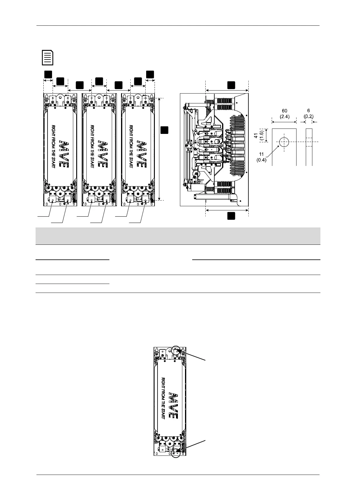
For these models, terminations can be made at either end of the input and output busbars.
MVE-0070-V11 ~ MVE-0540-V11
88 132
(7.8)
(39.4)
(14.9)
MVE-0070-V13 ~ MVE-0540-V13
(12.1) (5.2)
(9.1)
(43.3)
(16.5)
MVE-0600-V11 ~ MVE-1700-V11
For typical values, please consult AuCom
MVE-0600-V13 ~ MVE-1700-V13
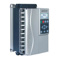
6.6 Earth Terminations
Models V02~V06 do not include earth studs.
Models V11~V13 have two 10 mm earth studs, at the rear of each phase arm close to the mounting points. Use only M10 high
tensile grade 8.8 threaded fasteners for all terminations. Use a pre-load torque setting between 28 ~ 30 Nm. Use only Belleville
washers.
A A
CC
B B
D
B
E
E
18969.B
2/T1
1/L1 3/L2 5/L3
4/T2 6/T3