APPENDIX
MVE User Manual (710-17074-00G) | 77
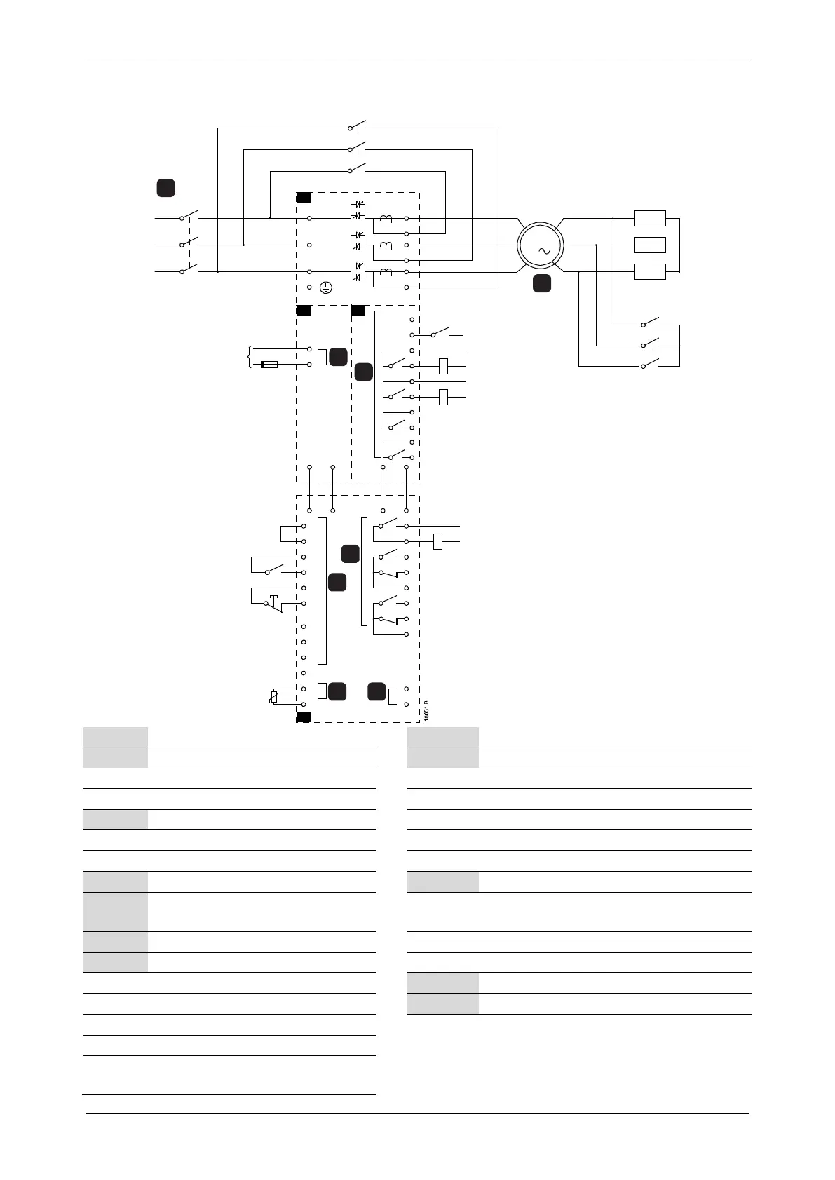
11.2 Slip-Ring Motor Connection
F1
-15
+10
K1
34
33
S1
S2
T3B
(Wh)(Bk)
(Bk)(Wh)
A4
A3A2
K2
T1B
T2B
T1
T2
T3
A1
A3
C23
C24
C31
C32
C53
C54
C63
C64
B4
B5
13
14
23
24
44
54
52
51
64
62
61
B10
B11
C41
C42
C74
C73
A11 A12
A11 A12
TX RX
RX TX
R1
K3
A1
E
L1
L2
L3
43
K2
3
M
+
-
K3
K1
K2
44
43
5
7
8
6
1
2
3
4
85-264VAC
or
90-350 VDC
Power assembly
Controller
3 Phase 50/60 Hz Supply
Remote control inputs
Motor
C41~C42 Control Input - Reset
R1 Slip-ring rotor resistance
C53~C54 Control Input - Programmable input A
Control Input - Programmable input B
Control voltage terminals
Programmable outputs
Control supply
43, 44 Relay output A
(7A= Changeover contactor)
Relay outputs
61, 62, 64 Relay output C
C73~C74 Bypass contactor feedback signal
Motor thermistor input
23~24 Bypass contactor K2
33~34 Run relay output
43~44
Phase arm power supply control relay
output



 To Next Page