APPENDIX
78 | MVE User Manual (710-17074-00G)
Using the MVE to Control a Slip-Ring Motor
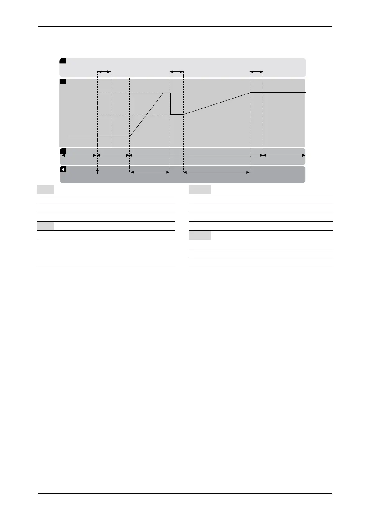
The MVE can be used to control a slip-ring motor, using rotor resistance.
03986.C
1
t1 t2 t3
2
V1
V2
S1
P1 P2 P3
S2 S3 S4
3
Sub-states
States
t1 Main contactor close time
S1 Ready
Rotor resistance contactor close time
Bypass contactor close time
Output voltage
S4 Running
V1 100% voltage
Phases of operation
Rotor resistance current ramp
P3 Shorted rotor current ramp
• Commissioning
1. Configure the MVE as follows:
Parameter settings:
• Parameter 7A
Relay A Function
• Select 'Changeover Contactor'
• Parameter 7B
Relay A On Delay
• Set this to the maximum time (5m:00s).
• Parameter 12A
Motor Data-1 Ramp
• Select 'Dual Ramp' (for slip-ring induction motor control)
• Parameter 12C
Changeover Time
• Default setting is 150 milliseconds. Set this to a value just greater than the changeover contactor (K3) pole
closing time.
• Parameter 12D
Slip Ring Retard
• Default setting is 50%. Set this parameter to a value which is high enough to cause the motor to instantly
accelerate once the rotor resistance (R1) has been bridged out and low enough to avoid a motor current pulse.
2. Start the motor under normal load conditions and record the time it takes to reach a constant speed with external rotor
resistance (R1) in the circuit. Stop the motor soon after a constant speed has been reached. Change parameter 7B to the
recorded time value.
3. Start the motor under normal load conditions and monitor the motor speed behaviour and motor current when the
changeover contactor (K3) switches in to short-out the rotor resistance (R1)
If the motor does not start to accelerate immediately after changeover, increase the setting of parameter 12D.
If there is a pulse in motor current immediately after changeover, reduce the setting of parameter 12D.



 To Next Page