INSTALLATION
MVE User Manual (710-17074-00G) | 25
6.13 CT Current Measurement
The MVE supports the summation and zero sequence methods of ground current measurement.
The line current transformers supplied with the soft starter are 1000:1 ratio. The MVE also supports customer-supplied 500:1 CTs
if required. If 500:1 CTs are used, the setting of switch S1 on the power interface board must be changed.
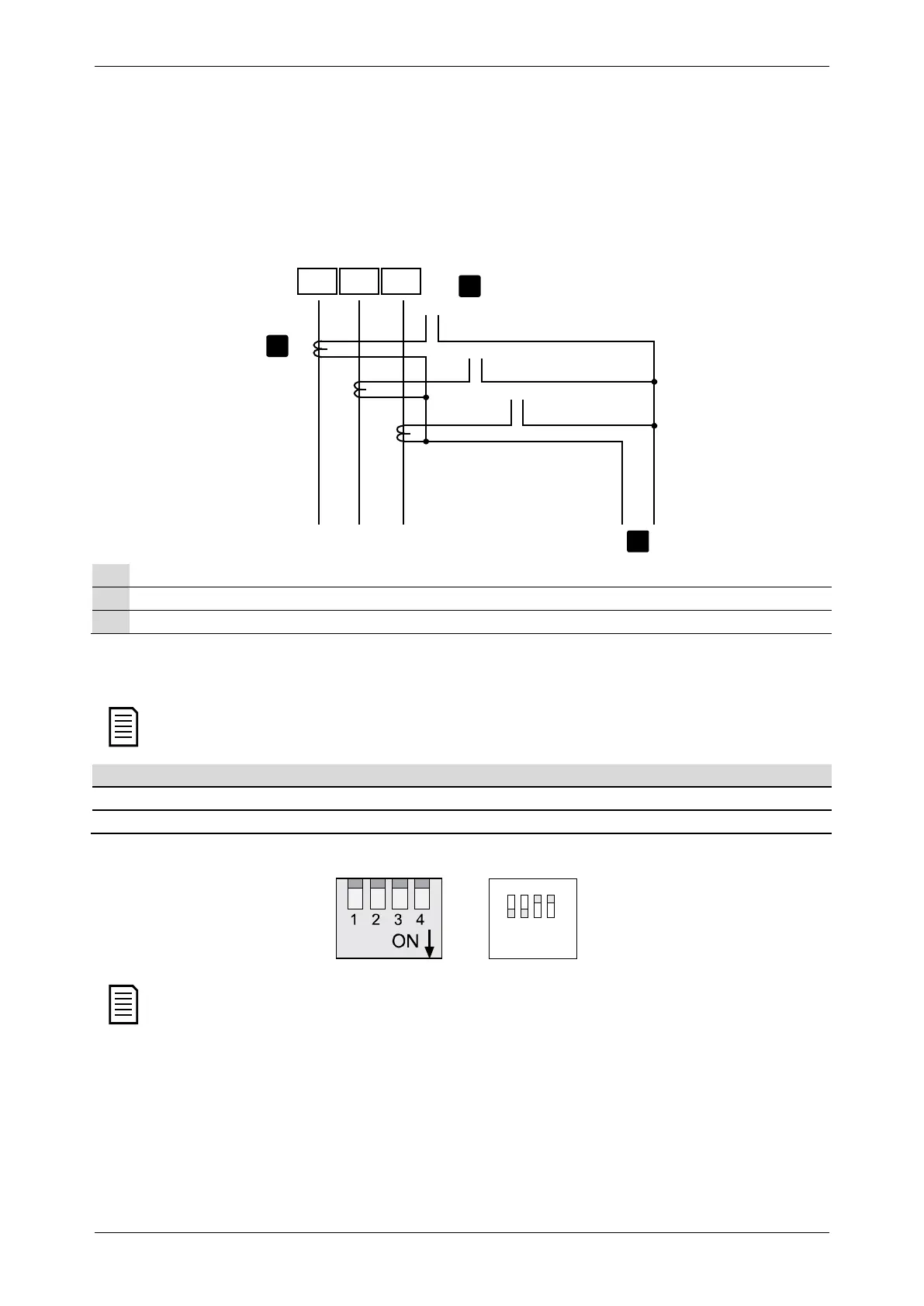
Summation method ground current measurement
• Connection diagram: ground current summation CTs
L1 L2 L3
L21
L22
L11
L12
L32
L31
GF2
GF1
2
3
1
17971.C
Line current transformers (1000:1)
Ground current input to Power Interface PCB
Individual phase inputs to Power Interface PCB
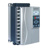
• Switch settings for summation method
The soft starter will check the switch settings when control power is applied. If the switch settings are changed, control
power must be cycled for the new setting to take effect.
500:1 0100
1000:1 1100
• Example settings for S1
Dip switch 1 on S1 is closest to the control terminal connectors. Dip switch 4 is closest to the CT connectors.