INSTALLATION
MVE User Manual (710-17074-00G) | 29
6.18 Internal Fibre-Optic Connections
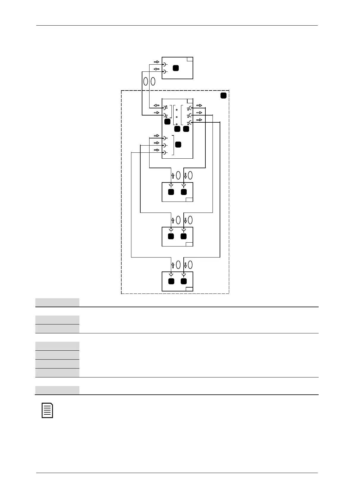
Internal fibre-optic cable connection diagram. This information is intended for panel builders.
RX
TX
PH1 PH2 PH3
PH1
PH2
PH3
TX
RX
A4
A3
A1-1
A1-2
A1-3
1
A
2
B
3C
DE
PH1
PH2
PH3
18359.A
4
3
2
1
76
6
6
5
7
7
8
Power assembly (including 3 phase arms)
Non-conduction PCBs mounted at bottom of each phase arm
Non-conduction [Tx] connector
Firing [Rx] connector
Non-conduction status LEDs (green)
Firing [Tx] connectors and Firing status LEDs (red)
Non-conduction [Rx] connectors
Connectors to controller [Rx, Tx] and status LEDs (green / red)
Controller
Connectors to interface PCB [Rx, Tx] and status LEDs (green / red)
The connector sockets for the fixed fibre-optic Transmit (Tx) and Receive (Rx) are mounted on the Interface PCB (A3)
and on the three Non-conduction PCBs (A1-1, A1-2 and A1-3).
• Transmit (Tx) fibre-optic sockets are light grey colour.
• Receive (Rx) fibre-optic sockets are dark grey colour.