CONTROLLER
MVE User Manual (710-17074-00G) | 51
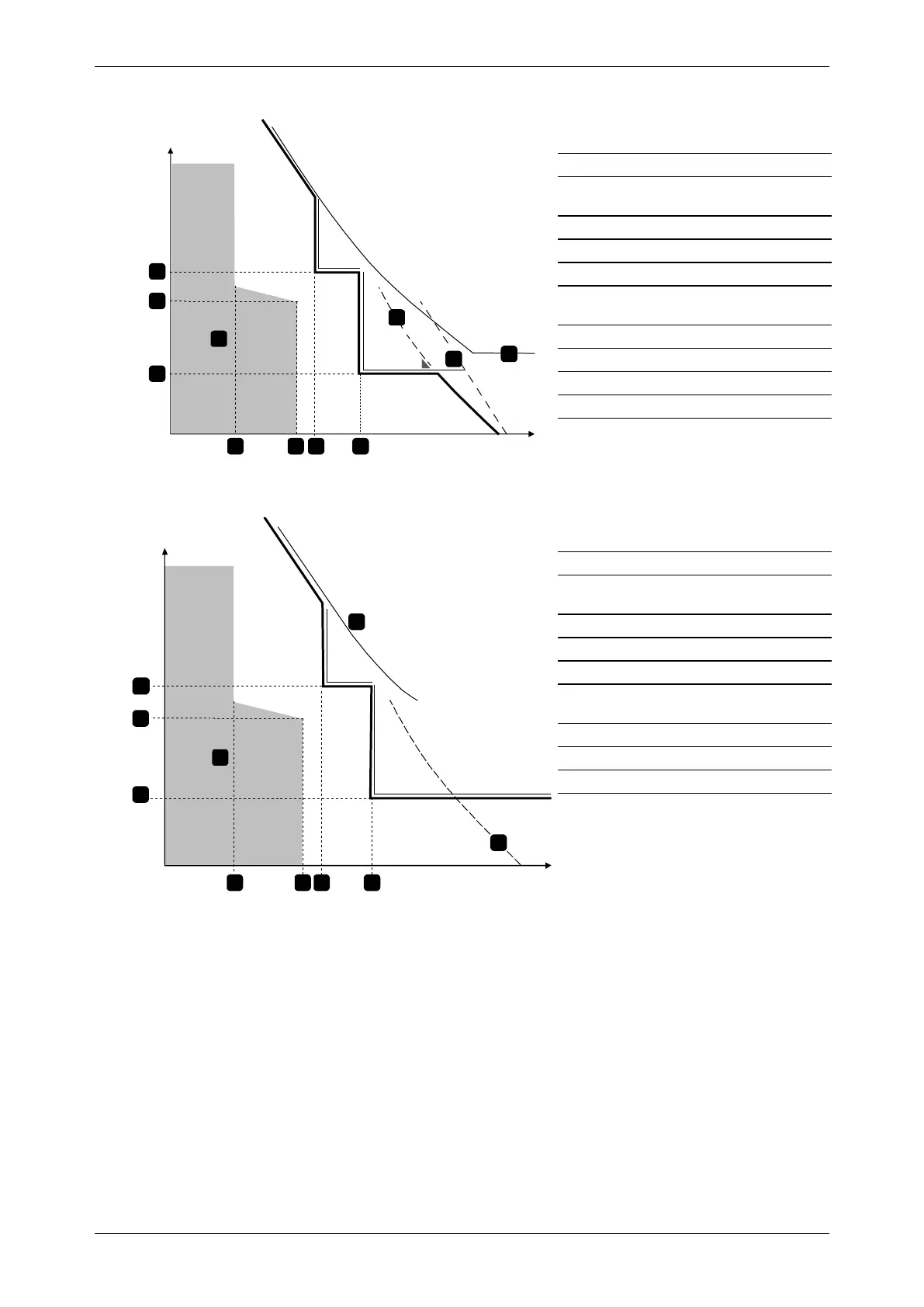
Example: Contactor and Fuse
Time
Current
Instantaneous Overcurrent Delay - Stage 1
(4F)
Motor start time
Instantaneous Overcurrent Delay - Stage 2
(4V)
FLC
Motor start current
Instantaneous Overcurrent- Stage 1 (4E)
Instantaneous Overcurrent - Stage 2 (4U)
to trip external upstream breaker
SCR
Thermal model curve
Motor operation (shaded area of graph)
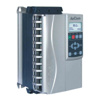
Example: Circuit Breaker
Time
Current
Instantaneous Overcurrent Delay - Stage 1
(4F)
Instantaneous Overcurrent Delay - Stage 2
(4V)
Instantaneous Overcurrent -Stage 1 (4E)
Instantaneous Overcurrent -Stage 2 (4U)
to trip main breaker
SCR
Thermal model curve
Motor operation (shaded area of graph)
5 Auto-Reset Trips (Reserved)
This parameter group is reserved for future use.