COMMISSIONING
MVE User Manual (710-17074-00G) | 63
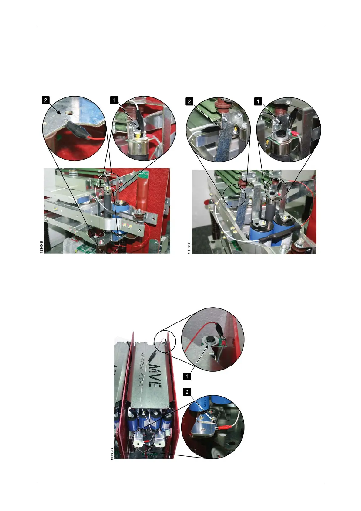
• Connect the LV motor test resistor assembly
MVE-0070~0540
1. Clip one end of the resistor assembly to the bolt on the non-conduction PCB. The non-conduction PCB is located on the
side of the phase arm, at the top of the long round grading resistor (refer to illustrations).
2. Clip the other end of the assembly to the steel bracket behind the grading resistor on the other side of the phase arm.
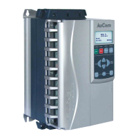
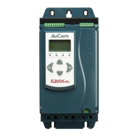
V02 V04~V06
MVE-0070~0540, V11-V13
1. Clip one end of the resistor assembly to the bolt on the non-conduction PCB. The non-conduction PCB is located at the
back right corner of the phase arm.
2. Clip the other end of the assembly to the busbar at the front left of the phase arm (refer to illustrations).