Copyright © 2007, 2008 AudioNote Kits
www.AudioNoteKits.com
audionotekits@rogers.com
Page 46
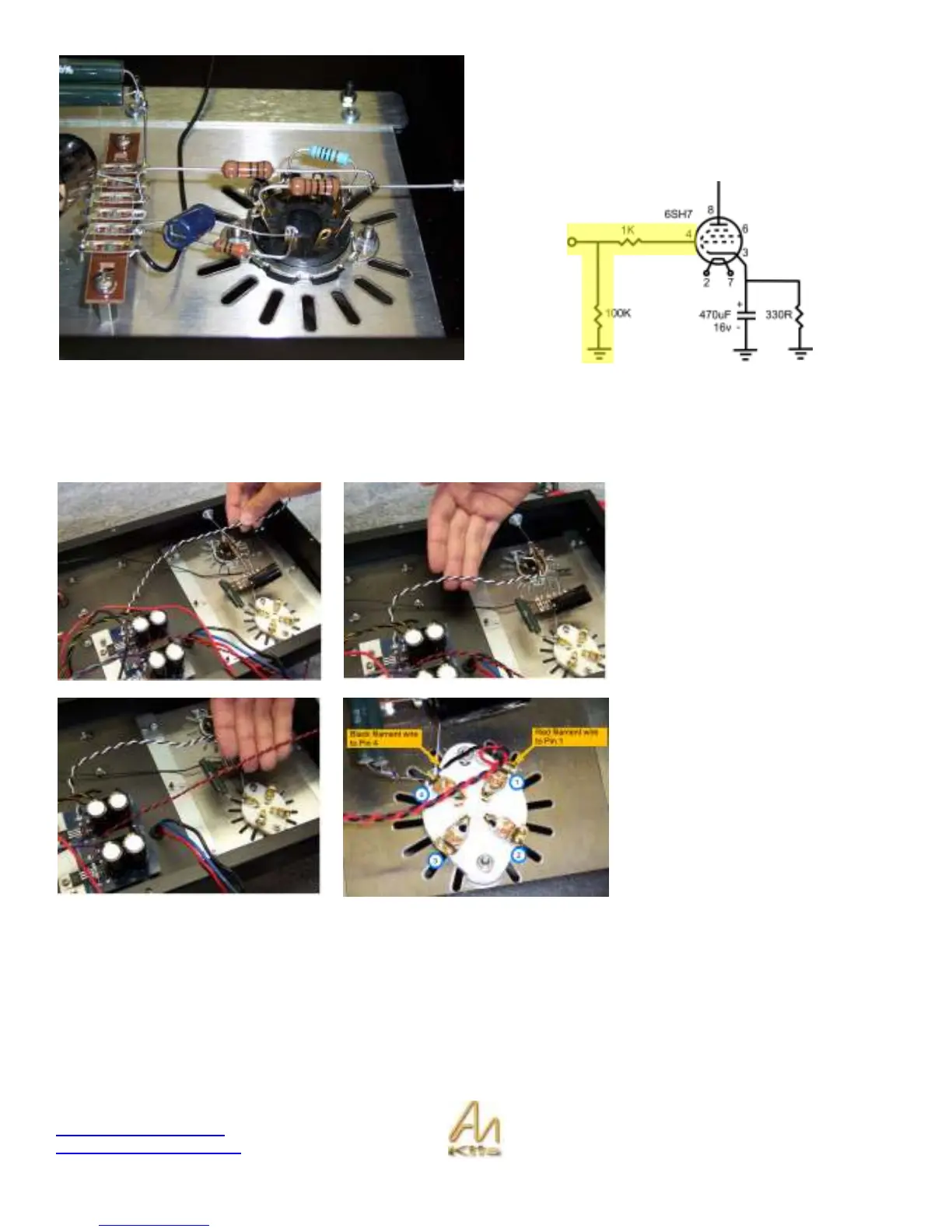
Now notice the 100K resistor goes from the input to GND –
wrap it around the input side of the 1K resistor we just
installed and connect the other end to the GND Tag strip.
The two resistors we have just installed appear as follows
(highlighted in yellow) on the signal path schematic.
With these 4 resistors installed on the 8-pin valve base we can move on!
Filament Wire Connections to 300B and 6SH7
Take the White/Black twisted wires
from the Filament board and connect
to pins 2 & 7 of the 8-pin valve base.
It does not matter which goes to which
pin – they will supply 6.3V DC to the
6SH7 and cause the tube to glow!
We are now going to install the red
black twisted filament wire to the 300B
tube valve base.
Connect the Red wire to pin 1 and the
Black wire to pin 4 – This will supply
the 5V DC to the 300B.