Copyright © 2007, 2008 AudioNote Kits
www.AudioNoteKits.com
audionotekits@rogers.com
Page 59
5Y3 Valve Base
Pin 1
Not connected
Pin 2 Yellow wire to Mains transformer secondary
Pin 3
Not connected
Pin 4 Red wire to Mains transformer secondary (for 300B operation)
- or - Orange wire to Mains transformer secondary (for 2A3 operation)
Pin 5
Not connected
Pin 6 Red wire to Mains transformer secondary (for 300B operation)
- or - Orange wire to Mains transformer secondary (for 2A3 operation)
Pin 7 Not connected
Pin 8 Yellow wire to Mains transformer
Also to Power supply 220K
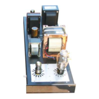
If all these connections look good then let's check over our Power Supply Wiring next – View the Power Supply Graphic
and double check all connections.
Now check the Polarity of all the electrolytic capacitors – Start with…
• 220uf 100v on the 300B valve base
• The 2x 47uF 450v caps on the 220K – they should be + - + -
• Then check the 220uf 500V cap in the rear insert for polarity
Now check that the Mains transformer wiring is correct for your world voltage - 120 , 240 etc…
Resistance Checks
If you have an ohmmeter then it would be a good idea to make some initial ohm checks.
With your black probe on the Silver GND lug on the power supply and no tubes installed – use you red probe and check
on the power supply to the point where the red wire comes from pin 8 of the 5Y3 – This should be approx greater than 2M
ohm – it will bounce around due to the capacitors.
Check from pin 4 of the 300B to GND – 750R
Pin 3 of the 6SH7 – 330 ohms to GND
Check for 100ohms between the chassis GND (lug on the Mains) and the GND on the GND tag strip on the front insert
plate.