Do you have a question about the Audio Note EL34 and is the answer not in the manual?
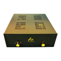
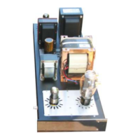
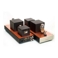
General welcome and overview of the AudioNote L4 Series EL34 Push-Pull Power Amplifier kit.
Crucial safety information regarding potentially harmful voltages within the amplifier kit.
Guidance on starting the build process, including chassis preparation and initial component mounting.
Instructions for attaching the four rubber feet to the amplifier chassis.
Mounting the IEC socket, rocker switch, and mains transformer onto the chassis.
Preparing the mains transformer's secondary wires for connection.
Step-by-step guide for assembling the amplifier's power supply board.
Mounting diodes, resistors, and capacitors onto the power supply PCB.
Detailed instructions for building the ECF80 driver board.
Installing valve base, resistors, and capacitors onto the ECF80 driver board.
Building the hardwired sections for the EL34 tubes on aluminum plates.
Mounting and wiring valve bases and components for the EL34 section.
Connecting the choke and high voltage leads from the mains transformer.
Routing and connecting the choke wires and high voltage AC leads.
Connecting filament power to the EL34 hardwired boards from the mains transformer.
Wiring the 6.3V AC filament supply to the EL34 valve bases.
Connecting the primary side of the output transformers to the EL34 boards.
Wiring the red and black wires from the output transformer primaries.
Connecting HT (High Tension) and Ground wires to the EL34 boards.
Routing and connecting high voltage (RED) and ground (BLACK) wires.
Connecting the output transformer secondary leads to the speaker posts.
Attaching speaker output leads to the rear chassis terminals.
Providing filament power to the ECF80 driver boards.
Connecting filament wires and DC voltage to the ECF80 driver boards.
Making the signal and control connections between driver and EL34 boards.
Wiring the interconnections between the ECF80 driver and EL34 boards.
Connecting the input RCA jacks and finalizing the chassis ground wiring.
Wiring the AN-A cable to RCA inputs and connecting chassis ground.
Procedure for initial power-up and testing of the completed amplifier.
Steps for safely applying power and testing the amplifier's functionality.
Supplementary information including color codes, diagrams, and schematics.
Guide to interpreting resistor color bands for component identification.
Diagram of the T190 transformer primary and secondary winding connections.
Schematic diagram for the amplifier's power supply board.
Circuit schematic for the ECF80 driver board.
Circuit schematic for the EL34 output board.
Wiring diagram for the EL34 output section's hardwiring.
Overall wiring diagram showing connections between all major amplifier components.
Complete circuit schematic of the AudioNote L4 Series EL34 Amplifier.
| Type | Integrated Amplifier |
|---|---|
| Tube Type | EL34 |
| Signal to Noise Ratio | 90dB |
| Tube Complement | 2 x EL34 |
| Input Impedance | 100k Ohms |
| Output Impedance | 4Ω, 8Ω |