Do you have a question about the Audio Note Mono Block 300b/2A3 and is the answer not in the manual?
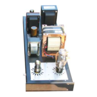
Describes left and right chassis differences and suggests a build order for the mono block.
Explains the provided hardware and the types of metric screws (M3, M4) used in the kit.
Outlines the general order of the build steps and offers encouragement for the assembly experience.
Details the process of fitting rubber grommets into the chassis for wire entry points.
Explains how to secure tang strips to hold the front and rear faceplates using M3 screws.
Guides the installation of the mains transformer, feeding wires through the chassis using rubber strips.
Instructs on matching and tidying transformer secondary wires with cable ties for neatness.
Describes installing two hardwiring posts using countersunk M3 screws into the chassis.
Details the mounting of the choke component using M4 nuts and washers.
Covers installing the 8-pin valve base, ensuring the notch faces correctly towards the chassis.
Guides the installation of flat screws for the heat sink that will be used later in the build.
Explains mounting the output transformer on top of the chassis with correct wire orientation.
Details the final mechanical step of mounting the interstage transformer, ensuring correct wire feed.
Guides the installation of the IEC inlet plug and mains rocker switch into the chassis.
Details connecting the green wire and transformer ground wire to the IEC plug's GND post.
Explains wiring the mains primary wires to the rocker switch for 120V operation.
Covers connecting the brown/blue wire to the IEC plug and tidying the primary wires.
Guides the hardwiring of the power supply using tag strips and components like capacitors and resistors.
Details specific wiring for the parallel triode version, adding resistors for filament supply.
Guides the installation of bridge rectifiers and polarized electrolytic capacitors onto the filament board.
Details installing resistors and connecting wires to the filament board's terminals.
Guides the proper installation of LM1084 voltage regulators onto the board and heatsink.
Explains connecting transformer secondary wires to the filament board for tube power supply.
Describes installing grommets and mounting the filament board onto the chassis heatsink.
Details securing the regulator to the heatsink to ensure proper heat dissipation.
Explains the pin-out and orientation for the 300B valve base to ensure correct connections.
Guides the installation of 4-pin and 8-pin valve bases and the tag strip onto the front insert plate.
Details creating a ground bus by wiring a silver wire to the tag strip for common earth connection.
Provides a detailed wiring diagram for components mounted on the front insert plate.
Covers connecting resistors and capacitors to the 8-pin valve base (6SH7).
Shows how to prepare two 1K5 wirewound resistors for parallel connection.
Guides the installation and securing of the completed front faceplate into the chassis.
Details connecting a black wire from the RCA input ground to the tag strip on the insert plate.
Covers installing speaker posts and connecting output transformer wires based on impedance.
Guides connecting filament wires from the board to the 300B and 6SH7 valve bases.
Explains connecting the primary wires of the output transformer to the chassis and power supply.
Details connecting the four colored wires from the interstage transformer to various points.
Covers extending and connecting the white wire from the interstage transformer via a resistor.
Details connecting the red wire to the 8-pin valve base and the black wire to the 15K resistor.
Guides connecting the blue wire from the interstage transformer to the GND tag on the front insert plate.
Provides methods for cleaning up and securing unused transformer wires within the chassis.
Lists essential items to check for correct wiring before powering on the amplifier.
Reviews major wiring connections in the kit for accuracy.
Details the procedure for powering on the amplifier and checking tube illumination.
Explains how to use the provided kit for audio signal and hum testing.
Discusses checking and adjusting for different world AC wall voltages.
Guides the installation of rubber feet and the base plate onto the amplifier bottom.
Describes expected humming during turn-on and its resolution.
Concludes the manual, congratulating the builder and providing contact information.
Explains how to read resistor color codes for component identification.
Provides diagrams for mains wiring configurations for various world voltages.
A schematic diagram detailing the front plate wiring connections.
A detailed schematic of the power supply circuit for the amplifier.
A schematic illustrating the signal path for the single 300B configuration.
A schematic illustrating the signal path for the parallel 300B configuration.
| Brand | Audio Note |
|---|---|
| Model | Mono Block 300b/2A3 |
| Category | Amplifier |
| Language | English |