Copyright © 2007, 2008 AudioNote Kits
www.AudioNoteKits.com
audionotekits@rogers.com
Page 33
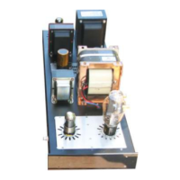
Here, you can see the 4 capacitors installed into position.
The next step is to install the Twisted wire provided in the
kit Filament Kit Bag.
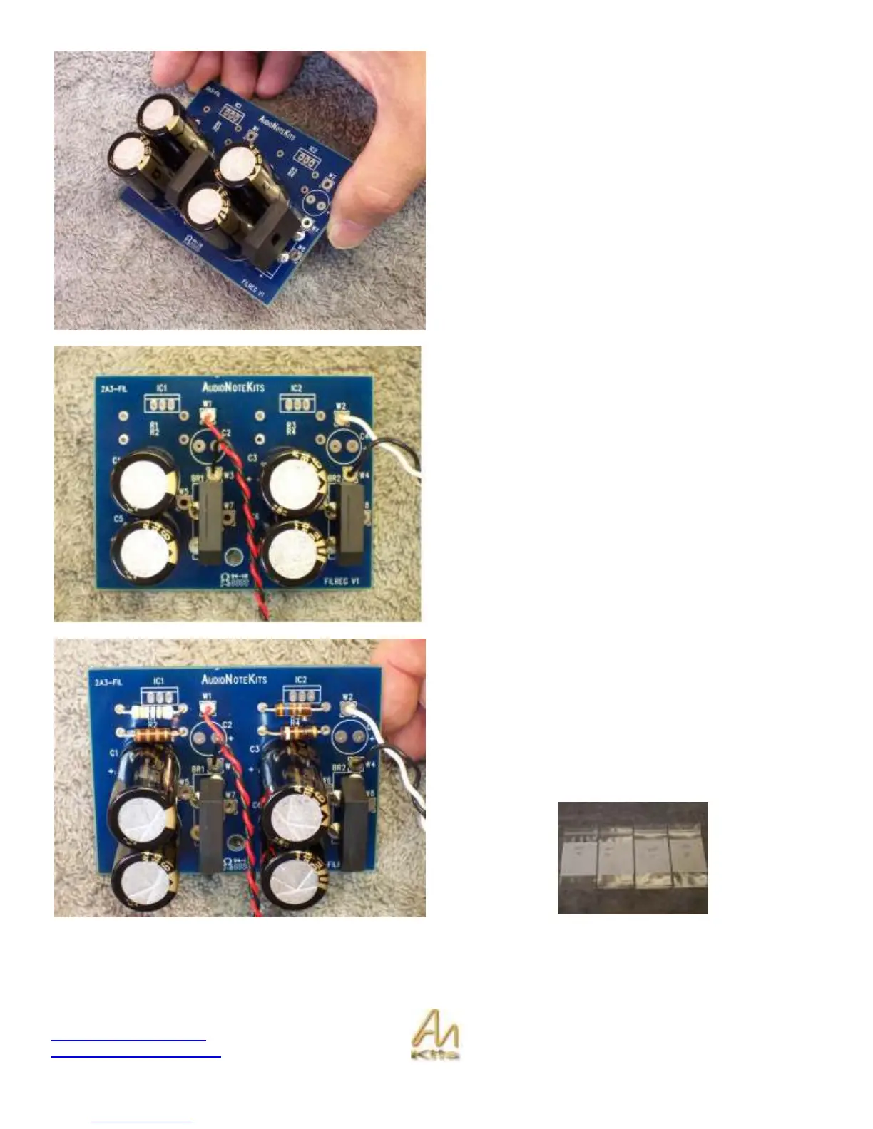
Install the Red/Black twisted wire in W1 (Red) and W3
(Black). This is the output of the filament board that will
carry the 5V DC to the 300B tube. Solder these wires on
the underside of the board and clip off any extra
White/Black twisted wire install in W2 (White) and W4
(Black) – solder underside of the board etc. as in previous
instruction.
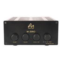
Our next step is to install the 4 resistors that have been
provided in the Filament Kit Bag.
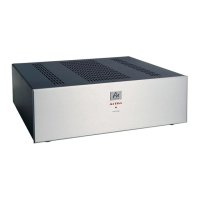
The Bags have the value of the resistor and the reference
designator (R1 R2 R3 R4). If you have an ohm meter you
could check that the value of the resistor matches the bag.
Then solder these 4 resistors into position. The ratio of
these resistor values is what set the filament DC voltage
that the filament board generates.
READ THE ENTIRE REMAINDER OF THIS CHAPTER BEFORE PERFORMING ANY MORE WORK – This is a tricky
part and requires concentration and no interruptions!