Copyright © 2006-2009 AudioNote Kits
www.AudioNoteKits.com
audionotekits@rogers.com
Page 19
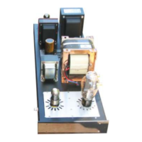
Installing the Resistors
Install the resistors into their correct positions on the board.
Refer to the parts list on the previous page. It’s also a good
idea to use an OHM meter and refer to the color code chart
for inserting the correct resistors into position.
NOTE: In the picture opposite we have also installed the 2
x .22 film caps into position – you can do this later in the
capacitor section. For now just concentrate on the resistors.
NOTE: R12 and R13 should be replaced with wire links as
these resistors have been relocated to the Output board for
performance reasons.
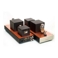
You will want to bend the legs to fit into position and then
solder on the underside of the board.
Here you can see the underside of the board – good idea to
do a double check on your resistor values once they are
inserted prior to soldering into position – check with the
schematic and the color code chart to make sure it all
makes sense!
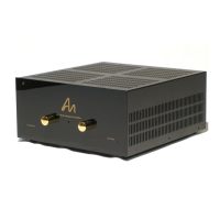
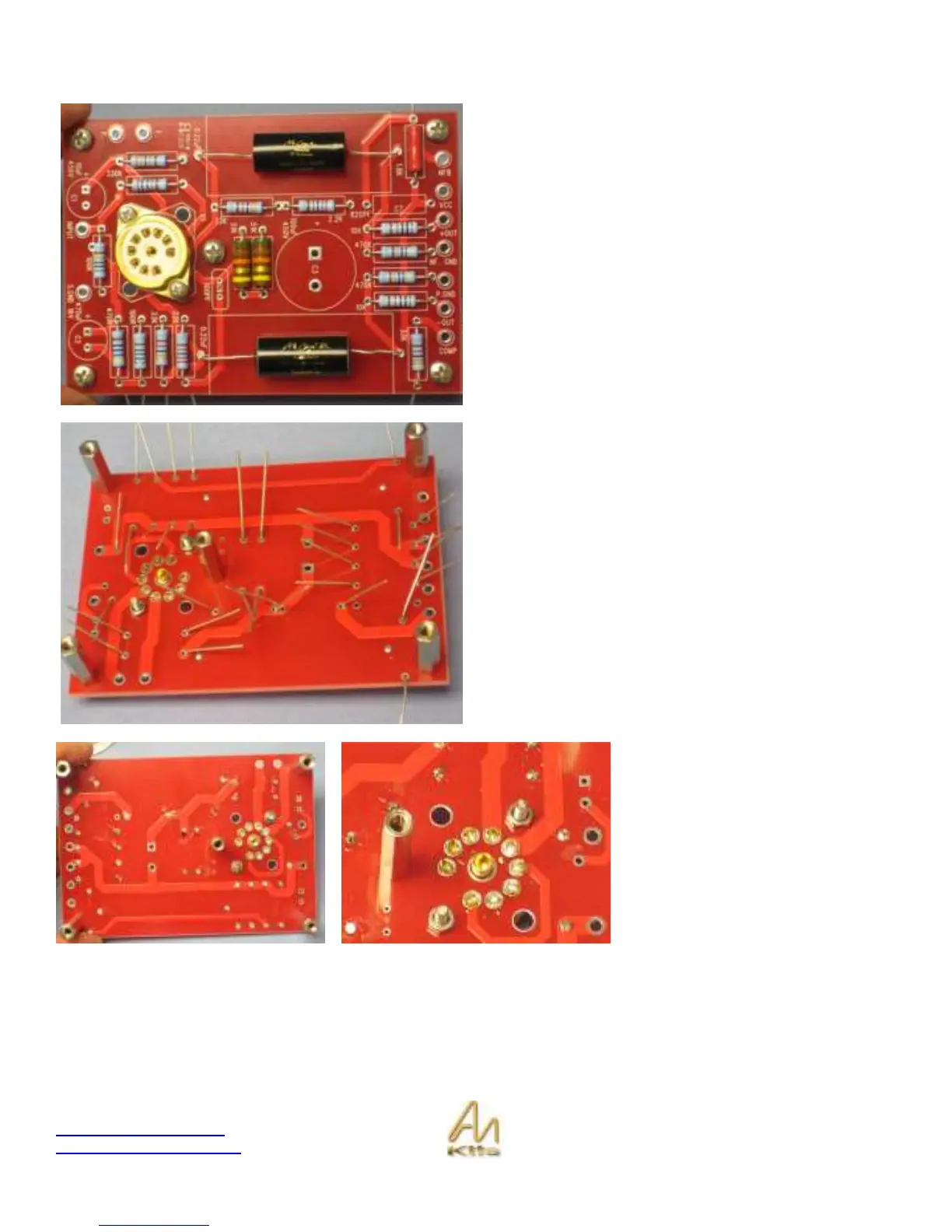
These two pictures show the
underside of the board with the valve
base soldered into position and the
resistor leads clipped!