Copyright © 2006-2009 AudioNote Kits
www.AudioNoteKits.com
audionotekits@rogers.com
Page 30
Section 7: Layout Recap
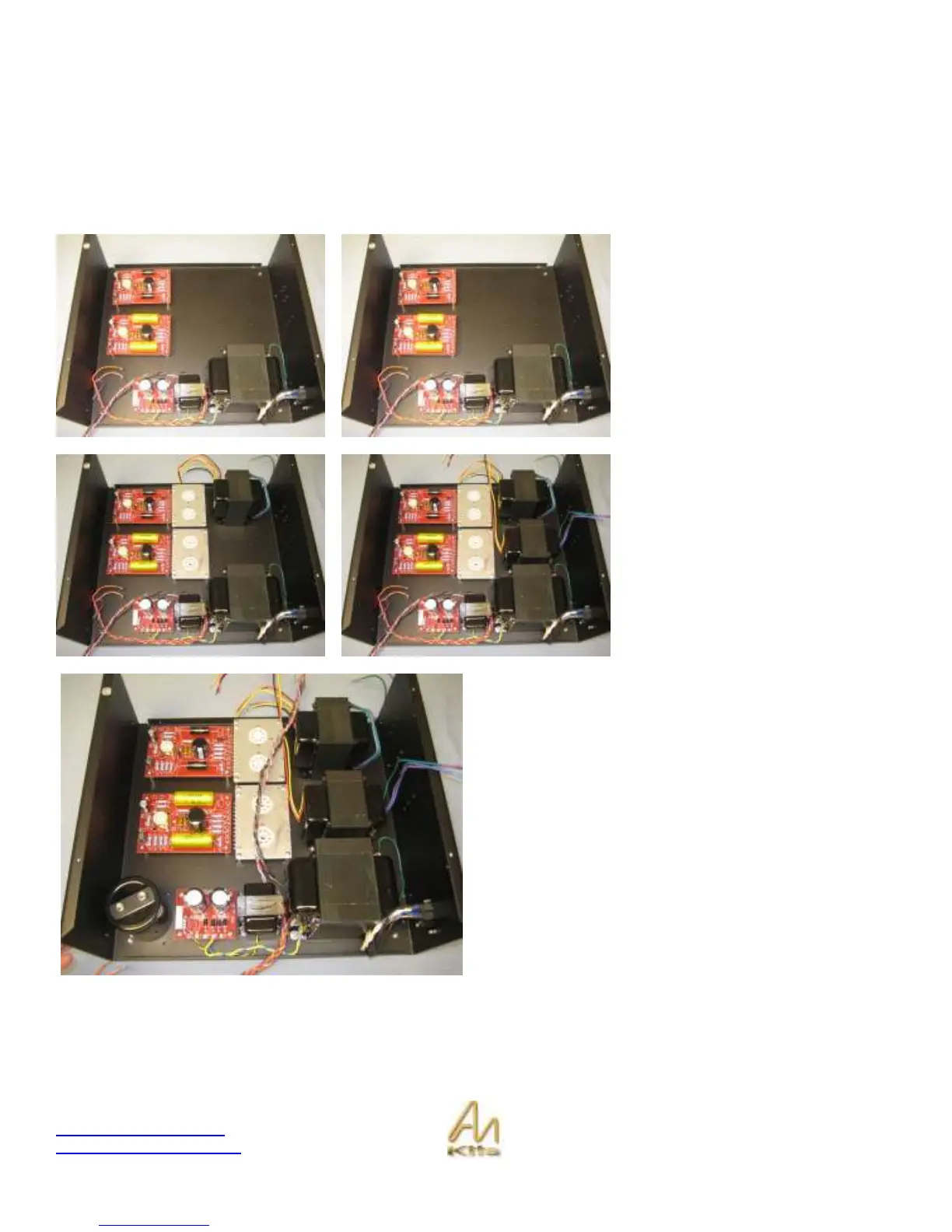
In this short section, we are going to review the layout of the internals of the amplifier. This will help you to understand the
wiring that you will have to perform later. For now, don’t screw any of the boards into place as you will need to have them
free in order to solder connections to them - often from the underside.
So, let’s have a quick look at the overall layout of the amplifier...
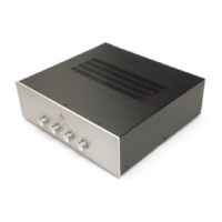
On the far left you can see the two
ECF80 driver boards installed into the
chassis – no need to secure any of
these boards as we will be wiring
underneath them later on.
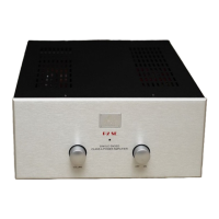
In the next picture we have positioned
the EL34 Hardwire Boards into
position – note that the tag strip is
closest to the ECF80 driver board.
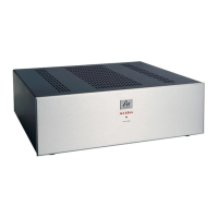
Here you can see the position of the
output transformers with the yellow
wires towards the center of the chassis
as these are the primaries – the green
blue purple wires are the secondaries
that will be connecting to the speaker
posts!
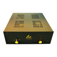
Here, you can see the position of the optional Mundorf Cap
for the power supply!
Ok with that lesson under out belt let’s move on to the next
section!