The Generator Only panel also allows control of the output
configuration. Subsequent presses of the bottom center soft key permit
selection between 40 Ω Unbalanced, 40 Ω Balanced, 150 Ω Balanced,
and 600 Ω Balanced configurations.
The upper center soft key allows control of the units for analog
generator amplitude.
Generator Loading
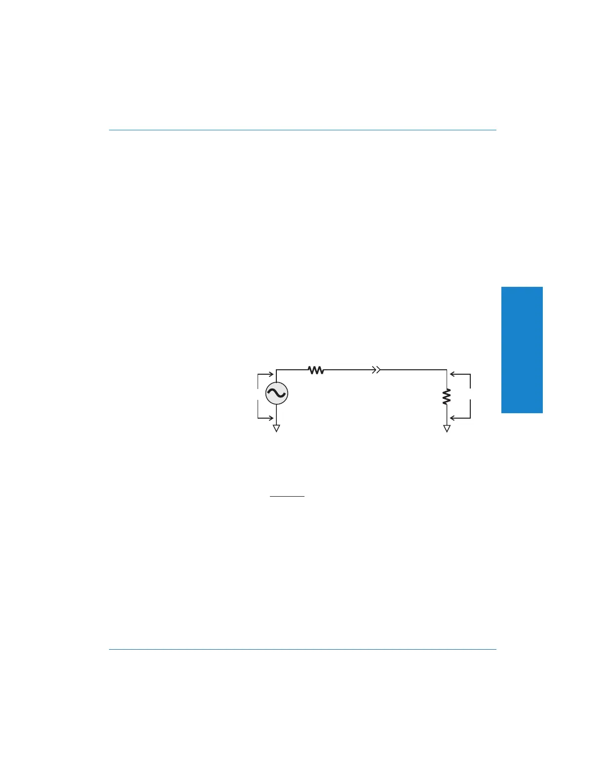
When a voltage unit (any unit besides dBm) is used, the generator
amplitude shown on the panel is the open-circuit voltage. Unless there
is no external load, the actual voltage at the load will be less than the
open-circuit voltage, since the selected source (output) impedance and
the impedance of the load will act as a voltage divider. The following
simplified schematic shows this relationship:
The voltage that will appear across the load can be calculated using the
following formula:
where Vl is the voltage across the load, Vs is the source voltage, Rl is
the load impedance, and Rs is the source impedance. For example, if
you output a 1 volt signal using the 40 Ω source impedance and load it
with the analyzer’s 100 kΩ load, the voltage across the load will be
0.9996 volts. As long as the load is 4 kΩ or higher, and the 40 Ω
source impedance is used, the load voltage will differ from the
open-circuit voltage by no more than 0.1 dB. For a 100 kΩ load,
typical of many professional audio devices, the 40 Ω source
impedance will cause an error of about 0.05 dB.
Vl Vs
Rl
Rl Rs
=•
+
enerator
Source
Impedance
DUT'S Load
Resistance
Vl
(Rs)
(Rl)
Vs
Generator
Source
Voltage
Generator
Output
Connector
Figure 4-10. Source and Load Impedances
& For a more
detailed
technical
diagram of the
Generator
output circuit,
4
Operation
Controlling the Generator : Generator Loading Operation
Portable One Plus Access User's Manual 4-13
Artisan Technology Group - Quality Instrumentation ... Guaranteed | (888) 88-SOURCE | www.artisantg.com