Connecting Mains Supply Voltage
Before plugging the unit in for the first time, it is a good idea to verify
that the power supply line voltage selection is correct. The units are
configured at the factory for the expected voltage at their intended
destination, so usually the voltage will be correct unless the unit has
been transported into another area.
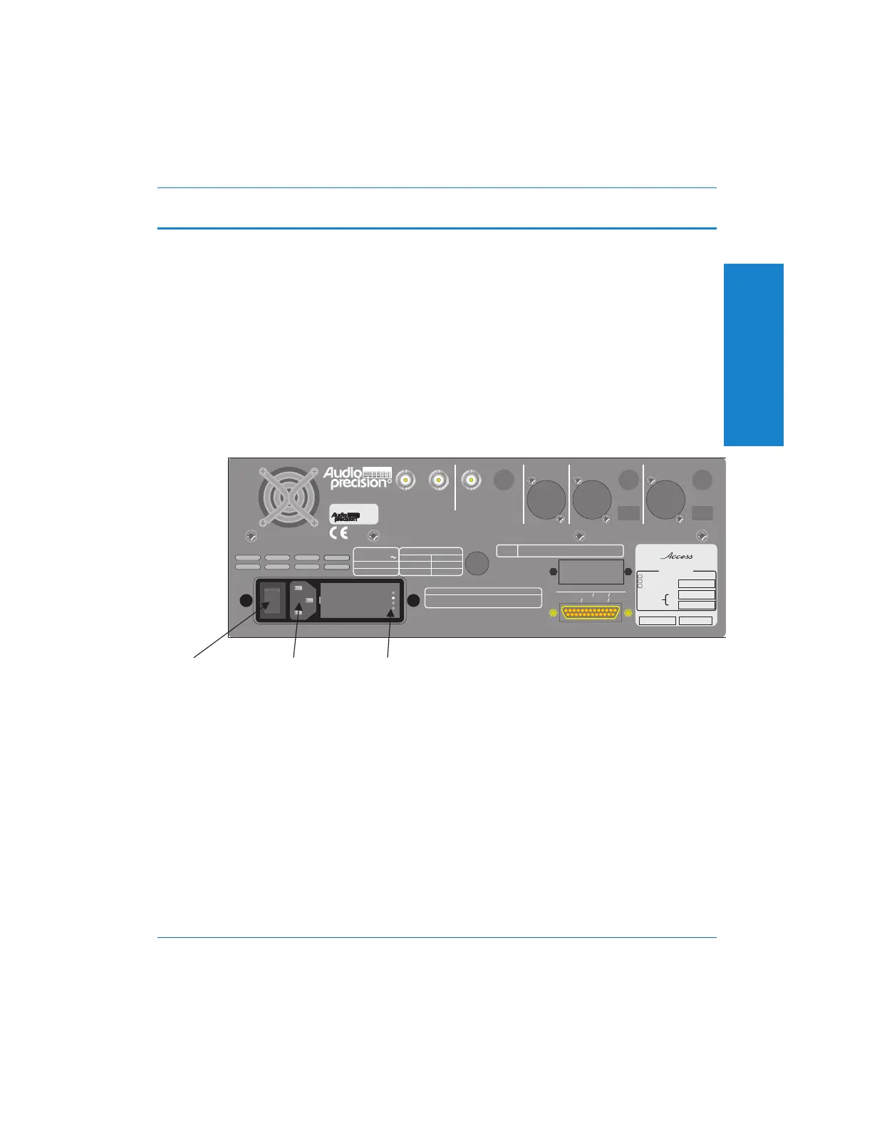
The supply voltage indicator is located on the rear panel of the
instrument next to the power plug. A small white plastic indicator tip
identifies the line voltage setting as 100V, 120V, 230V, or 240 V.
The following diagram shows the location of the voltage indicators:
In one of the holes should be a small white plastic indicator tip
showing which line voltage is currently selected. If the selected voltage
is not the same as the line voltage in your area, see Appendix D for
instructions on changing the line voltage selection.
Once the line voltage selection is correct, connect the line cord from
the power outlet to the power cord connector and move the power
switch to the ‘On’ position (marked ‘1’).
I
O
FUSE REPLACEMENT DATA
230/240 VAC
250mA T/SB 250V
100/120 VAC
500mA T/SB 250V
SUPPLY VOLTAGE
FUSE
MAXIMUM POWER: 60 VA
FREQUENCY: 50/60 Hz.
100/120/230/240 VAC
SUPPLY VOLTAGE:
TRIGGER SIGNALS
INPUT ANALOG DIGITAL
BAL
BAL
UNBAL UNBAL
5Vpp MAX
5Vpp MAX
OPTICAL OPTICAL
MONITORS
INPUT
REFERENCE DIGITAL OUTPUT DIGITAL INPUT
Manufactured in Beaverton, Oregon, USA
PARALLEL PRINTER
IEEE-488 INTERFACE
5,247,458; 5,420,516; 5,336,989. Other patent applications pending.
4,614,914; 4,563,652; 4,631,522; 5,089,981; 5,136,267; 5,265,201;
This product is protected by one or more of the following patents:
INSTRUMENT RESET
To restore factory default instrument settings,
hold dBr button and turn on mains power switch.
To set instrument GPIB address, use utility menu
under PANELS selection on front panel.
GPIB
ADDRESS
RL1, PP0, DC1, DT1, C0, E1
SH1, AH1, T6, TE0, L4, LE0, SR1,
PORTABLE ONE
R
ANALYZER
100 V
120 V
230 V
240 V
Date of manufacture Code
Audio Measurement System
PORTABLE ONE PLUS
Aux 2:
Aux 1:
Opt'l Filters:
Installed Options:
Special
EGZ Euro. Impedances
P1P-488 GPIB Inter.
P1-IMD Intermod. Distortion
LINE VOLTAGE
INDICATOR HOLES
POWER CORD
CONNECTOR
POWER
SWITCH
Figure 2-3. Location of Voltage Indicators
2
Getting Started
Connecting Mains Supply Voltage Getting Started
Portable One Plus Access User's Manual 2-3
Artisan Technology Group - Quality Instrumentation ... Guaranteed | (888) 88-SOURCE | www.artisantg.com