6
Part names and functions
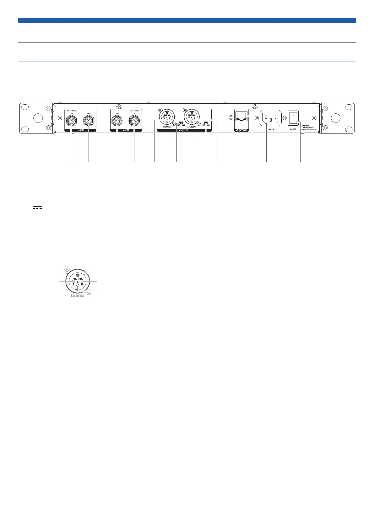
Rear panel
The figure below is of the ATW-DR3120.
❶ Antenna input jack
(
: This symbol indicates direct current.)
Each jack supplies 12VDC to a connected antenna.
Additionally, other compatible antenna accessories (sold separately) can be connected.
❷ Antenna output jack
Distributes and outputs signals input to antennas A and B.
By using this jack, it is possible to connect up to four receivers (five total).
❸ Balanced output jack (XLR 3-pin male)
GND
HOT
COLD
❹ Ground lift switch
This switch isolates the GND pin of the balanced/unbalanced output from the ground.
Normally this is kept in the GND position, but if a hum develops due to a ground loop, switch to the LIFT side.
❺ Network interface
By connecting to a PC via Ethernet, you can use the PC for monitoring or control.
In the case of the ATW-DR3120DAN, this can also double as a DANTE output terminal.
LAN: 100Base-TX
DANTE: 1000Base-T
❻ AC inlet
Connect the power cable.
(~: This symbol indicates alternating current.)
❼ Main power switch
Press to turn the power on/off.
❷❶ ❷ ❶ ❼❺ ❻❹❸ ❹ ❸
 Loading...