11
How to read the display
ATW-DR3120/ATW-DR3120DAN
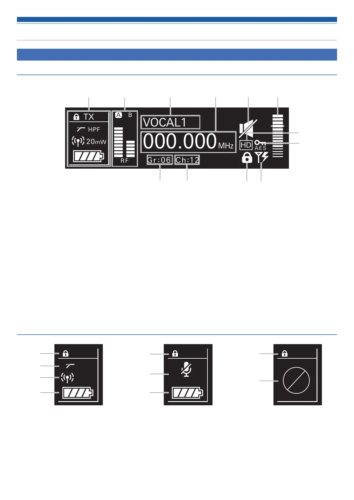
Main screen
TX
HPF
B
RF AF
0
000.000
VOCAL1
MHz
A
20mW
Gr 06 Ch 12
AE S
HD
❶ Transmitter information display area
Information on the connected transmitter is displayed. Refer to
“Transmitter information display area” (p. 11) for the screen display.
❷ RF level indicator
Displays the strength of RF reception for antennas A and B.
❸ Name display
Displays the specified name.
❹ Frequency indicator
Displays the set frequency.
❺ Receiver mute indicator
A speaker icon with a slash through it is displayed when the
receiver is muted.
❻ AF level indicator
Displays the strength of the received audio signal.
❼ Group indicator
❽ Channel indicator
❾ Lock status indicator
❿ Antenna input power indicator
An icon is displayed when the antenna input power supply is on.
⓫ AES-256 encryption mode indicator
⓬ HD mode indicator
Transmitter information display area
TX
HPF
20mW
❶
❷
❸
❹
TX
MUTE
❶
❺
❹
TX
❶
❻
Normal Muted Non-communication
❶ Lock status indicator
❷ High-pass filter indicator
❸ RF transmission output indicator
❹ Battery level indicator
❺ Transmitter mute indicator
A microphone with a slash through it is displayed when the
transmitter is muted.
❻ Transmitter non-communication indicator
❷ ❸ ❹ ❺ ❻
❼ ❽ ❾ ❿
❶
⓬
⓫
 Loading...