Fast Track Installation Guide 2. Installing the Mediant 2000
Version 4.6 13 July 2005
¾ With RJ-48c Connectors, take these 2 steps:
1. Connect the E1/T1 trunk cables to the ports labeled “Trunks 1 to 8” (in the case of the 8-
trunk device) on the Mediant 2000 RTM.
2. Connect the other ends of the Trunk cables to the PBX/PSTN switch.
RJ-48c trunk connectors are wired according to Figure
2-7 below.
Figure
2-7: Pinout of RJ-48c Trunk Connectors
1 2 3 4 5 6 7 8
3, 6, 7, 8
not connected
body = shield
1 = Rx Ring
2 = Rx Tip
4 = Tx Ring
5 = Tx Tip
RJ-48c Connector and Pinout
2.4.2 Installing the Ethernet Connection
Connect a standard Category 5 network cable to the Ethernet RJ-45 port (and the other as
optional redundancy/backup). Connect the other end of the Category 5 network cables to your IP
network. The Ethernet connectors (labeled Ethernet 1 and Ethernet 2) are wired according to
Figure
2-8.
Note that for redundant operation it is recommended to connect each of the Ethernet connectors
to a different switch.
When assigning an IP address to the Mediant 2000 using HTTP (under step
1 in Section 3.1.1),
you may be required to disconnect this cable and re-cable it differently.
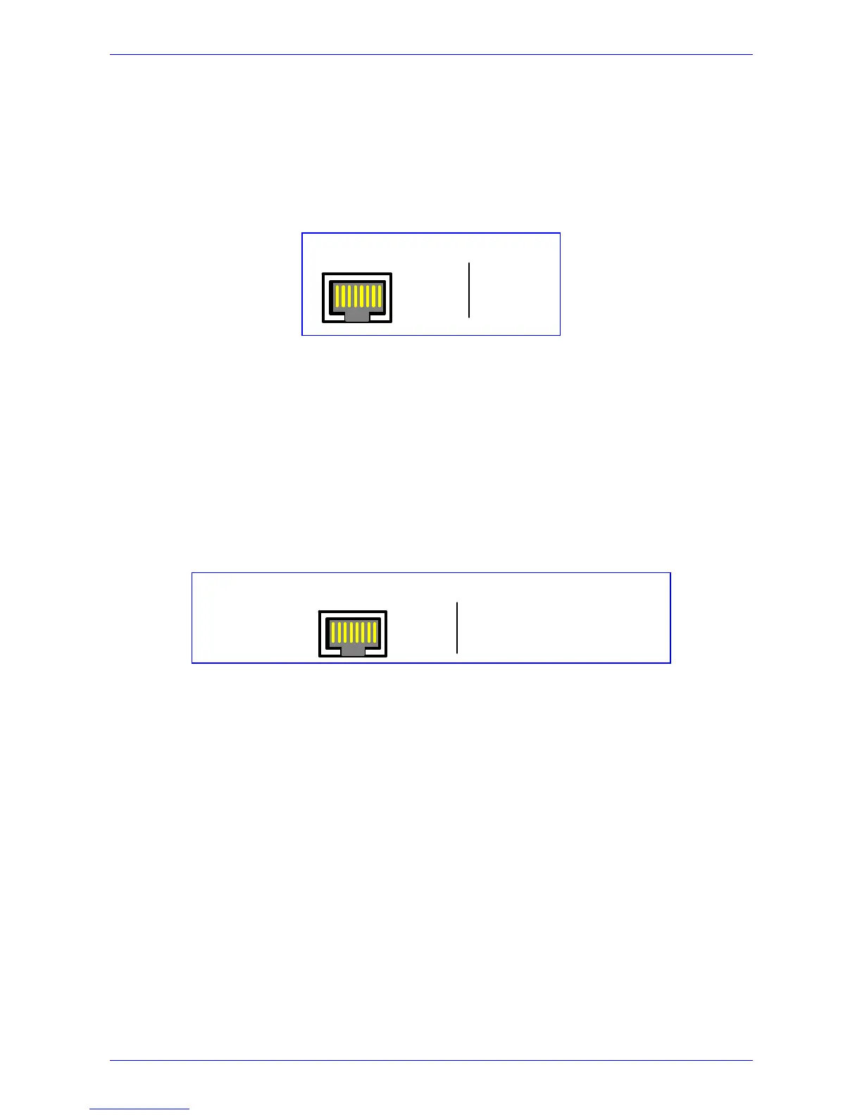
Figure
2-8: Pinout of RJ-45 Connectors
1 2 3 4 5 6 7 8
RJ-45 LAN Connector and Pinout
4, 5, 7, 8
not connected
1 = Tx+
2 = Tx-
3 = Rx+
6 = Rx-
2.4.3 Connecting the Power Supply
Connect the Mediant 2000 to the power supply using one of the following methods:
2.4.3.1 Connecting the AC Power Supply
¾ When using a single AC power cable:
Attach one end of the supplied 100/240 VAC power cable to the rear AC socket and connect the
other end to the correct earthed AC power supply.
¾ When using a dual AC power cable:
Before connecting the dual AC power cable, refer to the notes below.
Attach one end of the supplied 100/240 VAC power cables to the rear AC sockets and connect
the other end to a separate earthed mains circuits (for power source redundancy).

 Loading...


