Mediant 2000
Mediant 2000 32 Document #: LTRT-70105
6 Monitoring the Mediant 2000
The Mediant 2000 provides several ways of monitoring the status of the gateway:
• Monitoring the Mediant 2000 LEDs (refer to Section
6.1 below).
• Monitoring the Mediant 2000 trunks and B-channels via the Embedded Web Server (refer to
Section
6.2 on page 33).
6.1 Monitoring the Mediant 2000 LEDs
6.1.1 Mediant 2000 Chassis’ LED Indicators
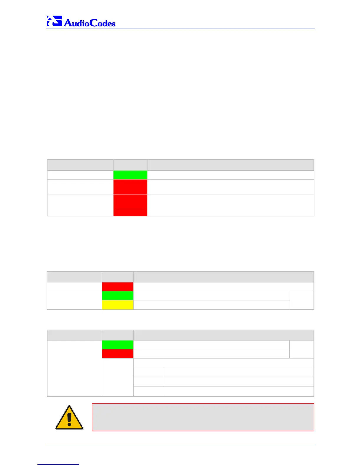
Table 6-1 provides a detailed description of the Mediant 2000 chassis’ LED indicators.
Table
6-1: Chassis LED Indicators
Location Color Function
Right side of front panel
Green
The power is on.
Right side of front panel
Red
Fan failure - indicates that any of the internal fans has
significantly reduced its speed or has frozen.
Left side of front panel
Red
Power supply failure - indicates that one of the two AC redundant
power supplies is faulty or disconnected from the AC/mains
outlet. (This LED is only relevant for the dual AC power supply).
6.1.2 TP-1610 Front Panel LED Indicators
The functionality of the front panel LEDs for the TP-1610 is described in the following four tables.
Note that there is a choice of front panels according to the number of channels.
Table
6-2: Status LED Indicators
Label LED Color LED Function
FAIL Red
Normally OFF; Red indicates gateway failure (fatal error)
Green
Gateway initialization sequence terminated OK
ACT
Yellow
N/A
Bi-color
LED
Table 6-3: E1/T1 Trunk Status LED Indicators
Label LED Color Signal Description
Green
Trunk is synchronized (normal operation)
Red
Loss due to any of the following 4 signals:
Bi-color
LED
LOS
Loss of Signal
LFA
Loss of Frame Alignment
AIS
Alarm Indication Signal (the Blue Alarm)
T1/E1 Status 1 to 8
and
T1/E1 Status 9 to 16
RAI
Remote Alarm Indication (the Yellow Alarm)
Note: On the front panel 16 LEDs are provided for 16-span units and 8 LEDs are
provided for 1-span, 2-span, 4-span, and 8-span units. In the case of 1-span,
2-span and 4-span units, the extra LEDs are unused.

 Loading...


