Version 6.0 13 February 2010
Installation Manual 2. Installing the Device
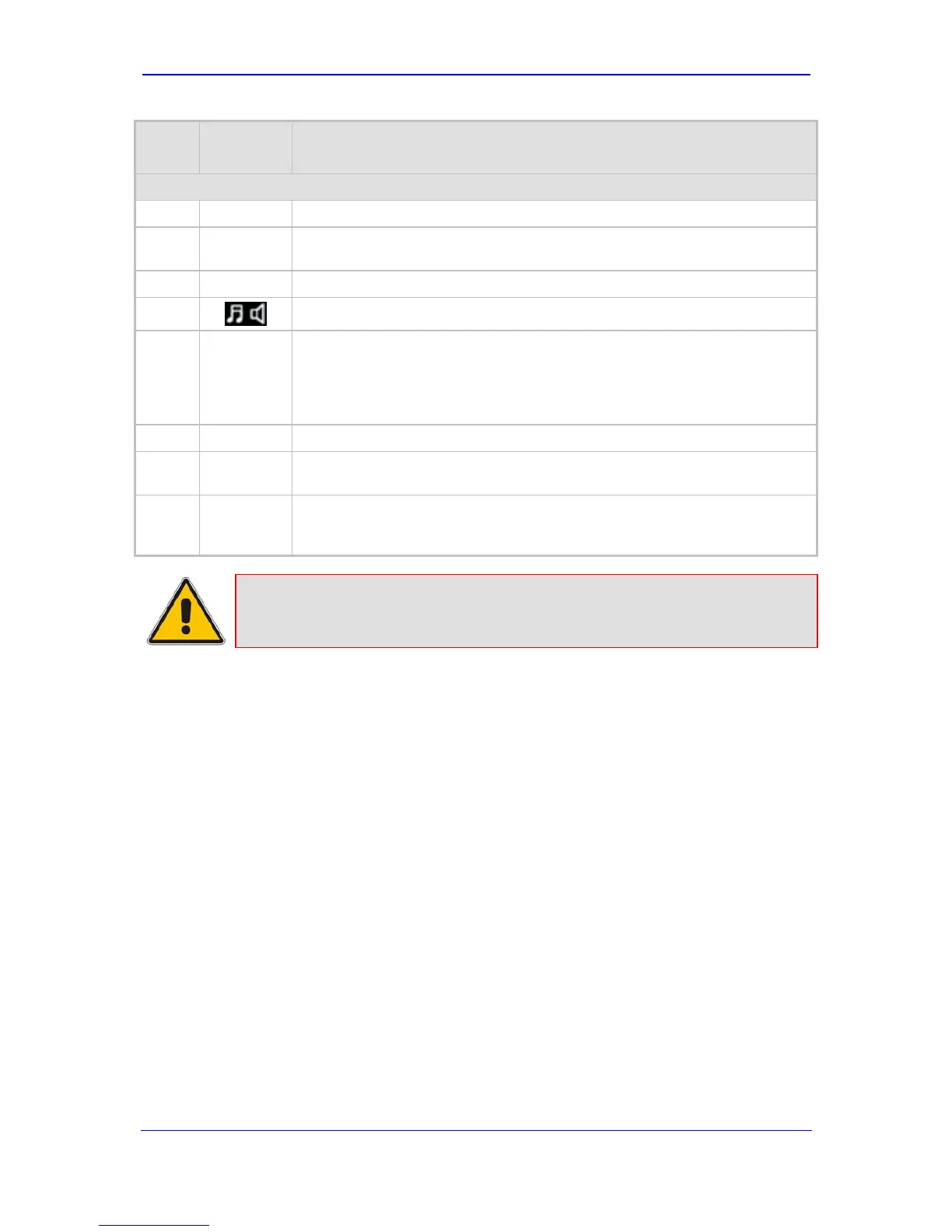
Item #
Label/
Module
Component Description
CPU - Enlarged View (#3)
8
-
Locking screws (2).
9
I
Dry contact port (normally open) - can be connected to an external audible or
visual alarm system (e.g., bell, siren, hooter, or light).
10
II
Dry contact port (normally closed).
11
Audio IN/OUT. (Currently, not applicable.)
12
I
10/100Base-TX Ethernet Port 1. Two Ethernet ports provide a dual Ethernet
redundancy scheme, protecting against failure such as a disconnection of any
cable or associated LAN switch port. These ports support auto-negotiation,
half- and full-duplex modes, and straight-through and crossover cable
detection.
13
II
10/100Base-TX Ethernet Port 2.
14
I0I0
RS-232 port for accessing the CLI and for receiving error / notification
messages. A 9-pin DB adaptor cable is supplied.
15
//
Reset button for resetting the device and optionally, for restoring the device's
parameters to their factory defaults (refer to ‘Restoring Factory Default
Settings’ on page 50).
Note: For module slot assignment, refer to 'I/O Module Slot Assignment' on page
29.

 Loading...


