Version 6.0 29 February 2010
Installation Manual 2. Installing the Device
2.5 Maintenance
This section describes the following maintenance operations:
Guidelines for I/O module slot assignment (refer to 'I/O Module Slot Assignment' on
page 29)
Repl
acing modules (refer to 'Replacing Modules' on page 30)
Insertin
g additional modules (refer to 'Inserting Modules into Previously Empty Slots'
on page 31)
Repl
acing the Fan Tray module (refer to 'Replacing the Air Filter' on page 32)
Note: Cover all unoccupied module slots in the front and rear panels of the chassis
with blank panels to maintain optimal internal airflow pressure within the
chassis.
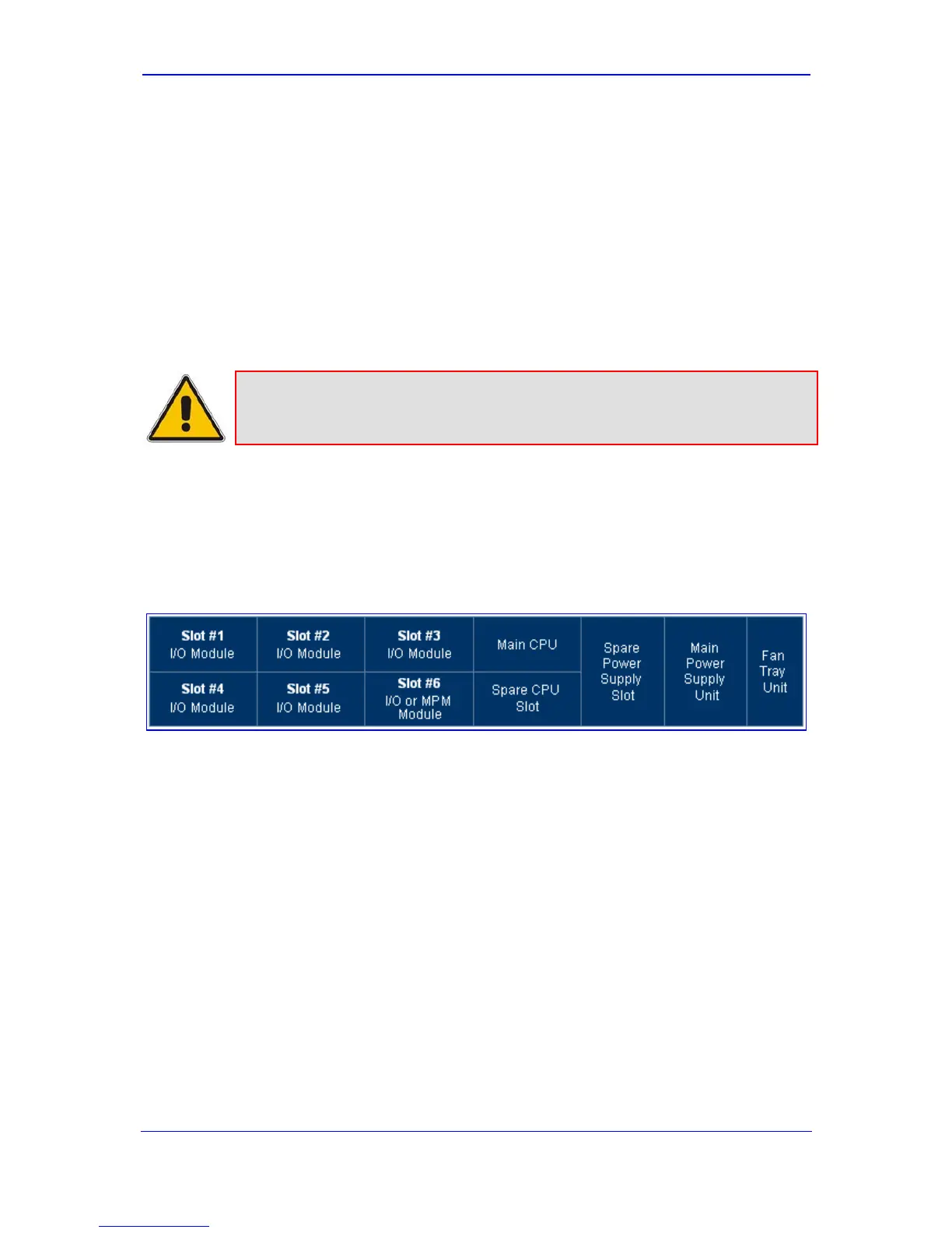
2.5.1 I/O Module Slot Assignment
The device's front-panel chassis provides slots (numbered as shown in the figure below) for
housing the main input/output (I/O) interface modules (i.e., TRUNKS, BRI, FXS, FXO, and
MPM).
Figure 2-17: Mediant 1000 Front Layout
The guidelines for slot assignment for these modules, include the following:
The TRUNKS, BRI, FXS, and FXO modules must be housed in consecutive slots. In
other words, if the device houses three modules, then they must occupy slots 1, 2, and
3 (no skipping of slots).
It is recommended to assign the TRUNKS, BRI, FXS, and FXO modules to the slots
(starting from Slot 1) according to the order of priority listed below:
1. TRUNKS
2. BRI
3. FXS and/or FXO

 Loading...


