5.3. Accessories for electrical connection
5.3.1. Actuator controls on wall bracket
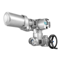
Design principle Figure 28: Design principle with wall bracket
[1] Wall bracket
[2] Connecting cables
[3] Electrical connection of wall bracket
[4] Electrical connection of actuator (XA)
[5] Electrical connection of actuator controls (XK) - customer plug
Application
The wall bracket allows separate mounting of actuator controls and actuator.
●
If the actuator cannot be accessed safely.
●
If the actuator is subjected to high temperatures.
●
In case of heavy vibration of the valve.
Observe prior to connec-
tion
●
Permissible length of connecting cables: max. 16 m.
Longer cables require an external filter (available on request)
●
We recommend using an AUMA “LSW” cable set.
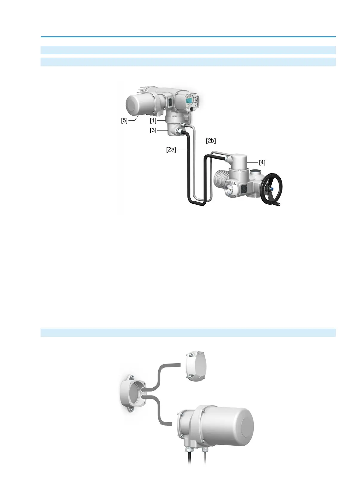
5.3.2. Parking frame
Figure 29: Parking frame, example with plug/socket connector and cover
33
SAV 07.2 – SAV 16.2 / SARV 07.2 – SARV 16.2 Control unit: electronic (MWG)
ACV 01.2 Modbus TCP/IP Electrical connection
 Loading...


