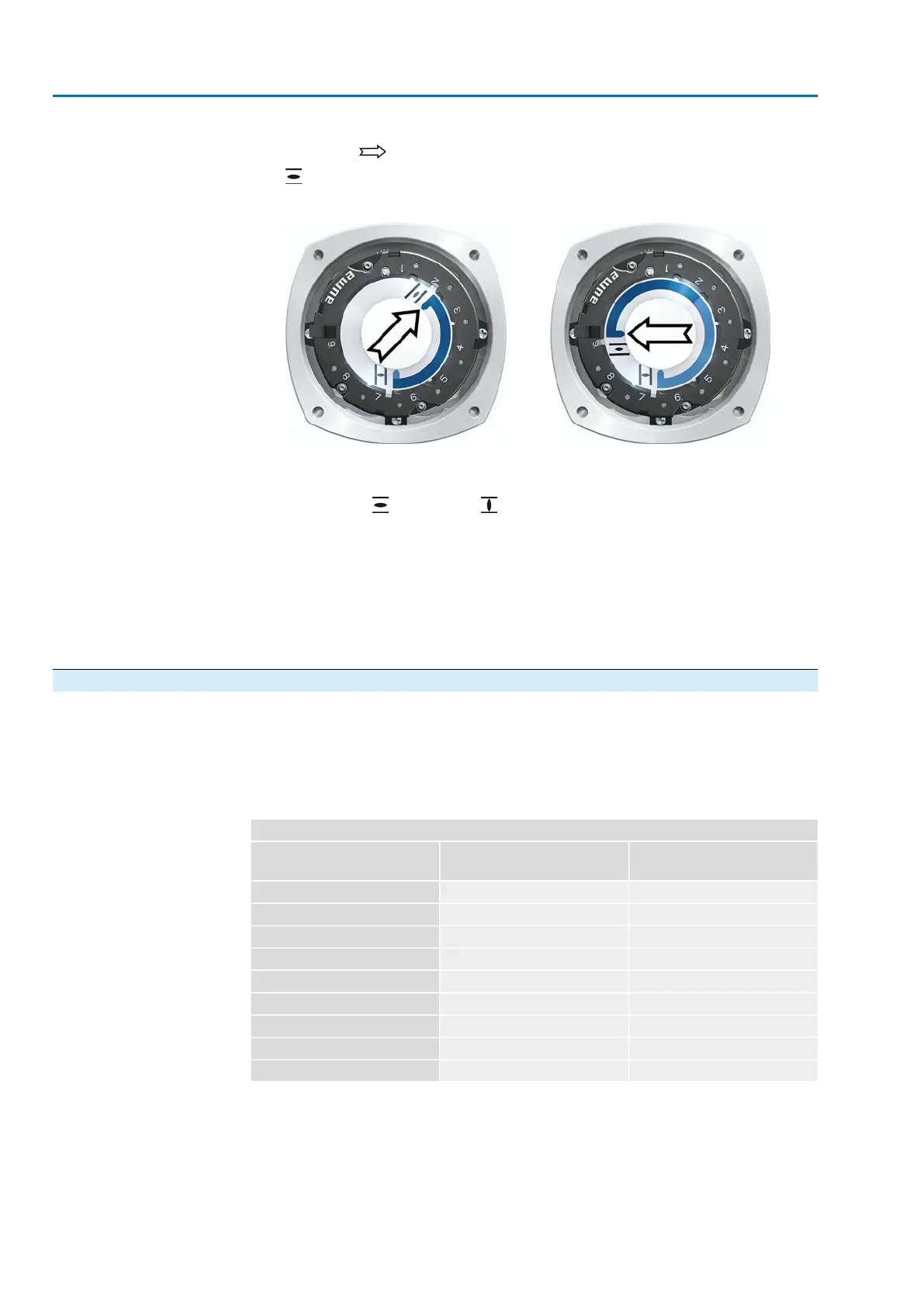
3. Move actuator to end position OPEN.
➥
The arrow rotates in direction OPEN driving the indicator disc with symbol
(OPEN) until the actuator stops in position OPEN.
Figure 72: Operation in direction OPEN (left) and position OPEN (right)
4. Check settings:
➥
The setting of the mechanical position indicator is correct if the angle between
the symbols (OPEN) and (CLOSED) ranges between approx. 120° and
280°.
➥
If all three discs are turned at the same time, the indicator can be shifted in
steps of 15°. Individual shifts of 5° are possible.
➥
If the indicator is rotated too far (more than 280°) or if the angle is too small
(below 120°), adapt the gear stage setting to the actuator turns/stroke. Refer
to <Gear stage of the reduction gearing: test/set>.
10.2.2. Gear stage of the reduction gearing: test/set
The test/setting is only required if the mechanical position indicator cannot be correctly
set.
1. Refer to table and check if turns/stroke correspond to the setting of the reduction
gearing (stages 1– 9).
Table 20:
Turns of actuator per valve stroke and suitable reduction gearing setting
Reduction gearing
Stage
for 10 – 5,000 turns/stroke
[exceeding – to]
for 1 – 500 turns/stroke
[exceeding – to]
110 – 191.0 – 1.9
219 – 371.9 – 3.7
337 – 793.7 – 7.9
479 – 1507.9 – 15.0
5150 – 31515.0 – 31.5
6315 – 60031.5 – 60.0
7600 – 1,26060.0 – 126
81,250 – 2,500126 – 240
92,500 – 5,000240 – 500
62
SAV 07.2 – SAV 16.2 / SARV 07.2 – SARV 16.2 Control unit: electronic (MWG)
Commissioning (settings/options in the actuator) ACV 01.2 Modbus TCP/IP
 Loading...


