3. Switch on actuator in direction CLOSE and observe direction of rotation at hollow
shaft [3] or stem [5]:
➥
The direction of rotation is correct if the actuator moves in direction CLOSE
and the hollow shaft in clockwise direction, or the stem moves downward.
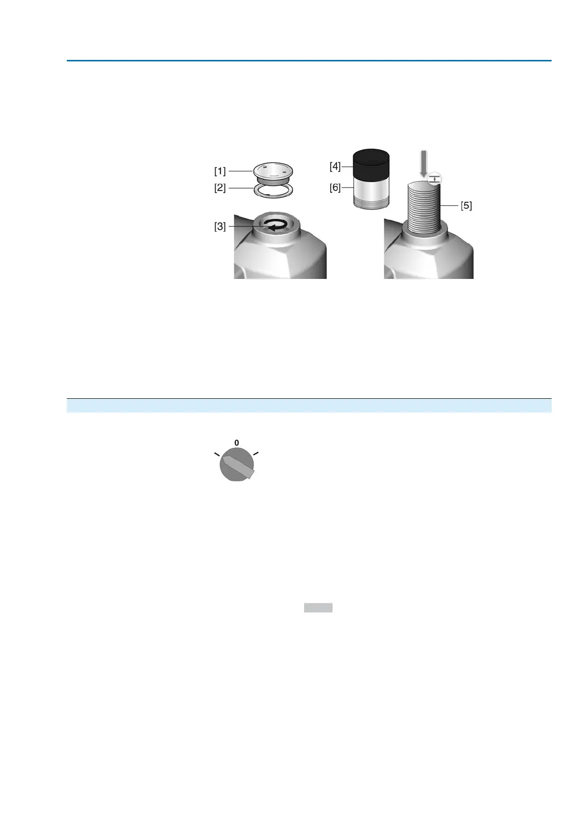
Figure 66: Hollow shaft/stem movement (for “clockwise closing”)
[1] Threaded plug
[2] Seal
[3] Hollow shaft
[4] Protective cap for stem protection tube
[5] Stem
[6] Stem protection tube
4. Correctly fit/screw on threaded plug [1] and seal [2] or protective cap for stem
protection tube [4], fasten thread.
9.6.3. Limit switching: check
1. Set selector switch to position Local control (LOCAL).
2. Operate actuator using push buttons OPEN, STOP, CLOSE.
➥
The limit switching is set correctly if (default indication):
- the yellow indication light/LED1 is illuminated in end position CLOSED
- the green indication light/LED5 is illuminated in end position OPEN
- the indication lights go out after travelling into opposite direction.
➥
The limit switching is set incorrectly if:
- the actuator comes to a standstill before reaching the end position
- one of the red indication lights/LEDs is illuminated (torque fault)
-
the status indication S0007 in the display signals a fault.
3. If the end position setting is incorrect: Reset limit switching.
59
SAV 07.2 – SAV 16.2 / SARV 07.2 – SARV 16.2 Control unit: electronic (MWG)
ACV 01.2 Modbus TCP/IP Commissioning (basic settings)
 Loading...


