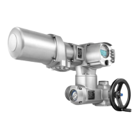
Features and functions
●
Electronic device ID with order and product data
●
Logging of operating data: A resettable counter and a lifetime counter each for:
-
Motor running time, number of starts, torque switch trippings in end position CLOSED, limit
switch trippings in end position CLOSED, torque switch trippings in end position OPEN, limit
switch trippings in end position OPEN, torque faults CLOSE, torque faults OPEN, motor protection
trippings
●
Time-stamped event report with history for setting, operation and faults:
-
Status signals according to NAMUR recommendation NE 107: "Failure", "Function check", "Out
of specification", "Maintenance required"
●
Torque characteristics (for version with MWG in actuator):
-
3 torque characteristics (torque-travel characteristic) for opening and closing directions can be
saved separately.
-
Torque characteristics stored can be shown on the display.
Diagnostic functions
Monitoring the motor temperature in combination with thermoswitches within actuator
motor
Standard:Motor protection evaluation
PTC tripping device (TMS module) in combination with PTC thermistors within actuator
motor
Option:
AUMA plug/socket connector with screw-type connectionStandard:Electrical connection
●
Terminals or crimp connection
●
Gold-plated control contacts (pins and sockets)
Options:
Metric threadsStandard:Threads for cable entries
Pg-threads, NPT-threads, G-threadsOptions:
Refer to name plateWiring diagram
For version with MWG within actuator
Setting of limit and torque switching via local controls
Via fieldbus interface
Galvanically isolated analogue output 0/4 – 20 mA (load max. 500 Ω).
Torque feedback signal
TPCHA000-1AF-A000 TPA00R100-0I1-000, 3-ph; 380 V – 480 V
TPCHA000-1AE-A000 TPA00R100-0I1-000, 1-ph; 220 V – 240 V
Wiring diagram (basic version)
Settings/programming the Modbus TCP/IP interface
Baud rate, parity and Modbus address are set via the display of actuator controlsSetting the fieldbus address
Settings are made via web server
Default settings of the IP interface:
IP Address Selection
Static IPAddress Type
192.168.255.1Static IP Address
255.255.0.0Subnet Mask
192.168.0.1Default Gateway
Setting the Modbus gateway
79
SAV 07.2 – SAV 16.2 / SARV 07.2 – SARV 16.2 Control unit: electronic (MWG)
ACV 01.2 Modbus TCP/IP Technical data

 Loading...