5. Electrical connection
5.1 Basic information
Danger due to incorrect electrical connection
Failure to observe this warning can result in death, serious injury, or property damage.
→
The electrical connection must be carried out exclusively by suitably qualified
personnel.
→
Prior to connection, observe basic information contained in this chapter.
→
After connection but prior to applying the voltage, observe the <Commissioning>
and <Test run> chapters.
Wiring diagram/terminal
plan
The pertaining wiring diagram/terminal plan is attached to the device in a
weather-proof bag, together with these operation instructions. It can also be obtained
from AUMA (state commission no., refer to name plate) or downloaded directly from
the Internet (www.auma.com).
Protection on site
For short-circuit protection and for disconnecting the actuator from the mains, fuses
and disconnect switches have to be provided by the customer.
The current values for respective sizing is derived from the current consumption of
the motor (refer to electrical data sheet) plus the current consumption of the controls.
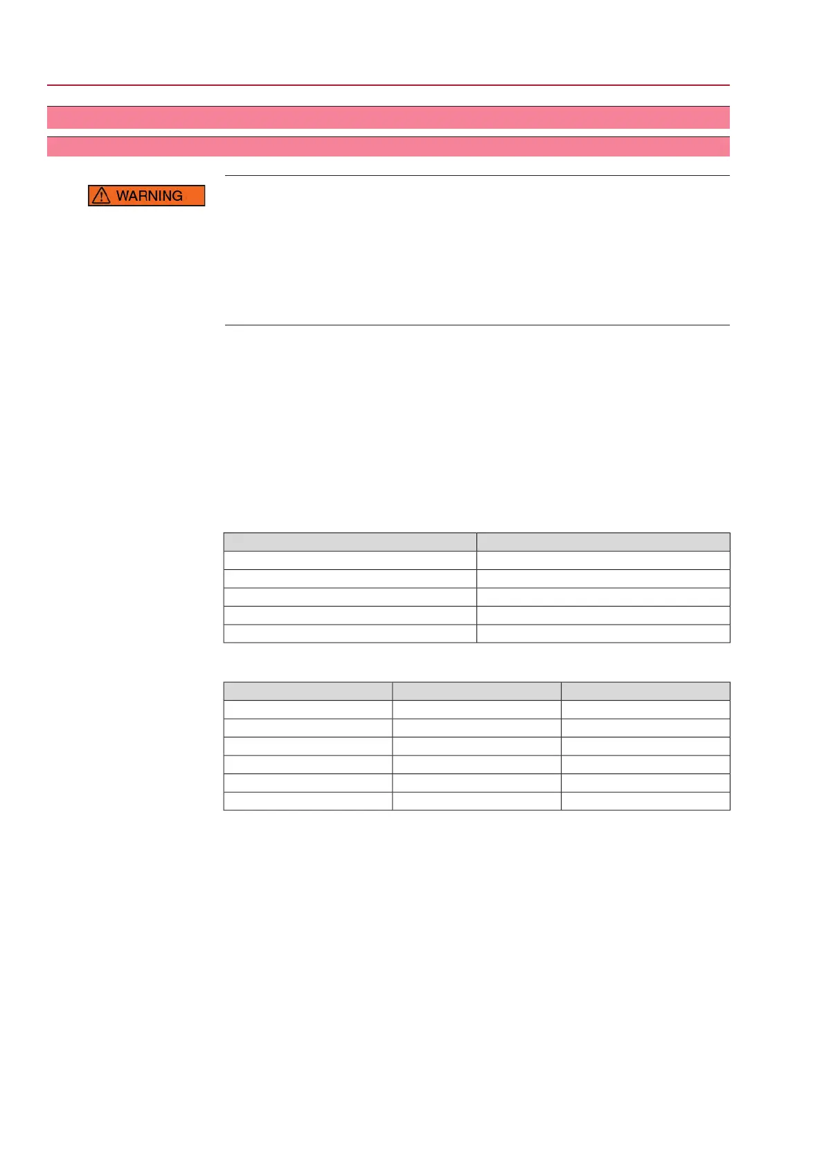
Table 3: Current consumption controls
Max. current consumptionMains voltage
650 mA100 to 120 V AC (±10 %)
325 mA208 to 240 V AC (±10 %)
190 mA380 to 500 V AC (±10 %)
500 mA, filter capacitor 2,200 µF24 V DC (+10 %/–15 %) and AC motor
750 mA, filter capacitor 2,200 µF24 V DC (+10 %/–10 %) and DC motor
Table 4: Maximum permissible protection
max. protectionRated powerSwitchgear
16 A (gL/gG)up to 1.5 kWReversing contactor
32 A (gL/gG)up to 7.5 kWReversing contactor
63 A (gL/gG)up to 11 kWReversing contactor
16 A (g/R) I²t<1,500A²sup to 1.5 kWThyristor
32 A (g/R) I²t<1,500A²sup to 3 kWThyristor
63 A (g/R) I²t<5,000A²sup to 5.5 kWThyristor
●
If controls are mounted separately from actuator (controls on wall bracket):
Consider length and cross section of connecting cable when defining the pro-
tection required.
●
Use appropriate earth leakage monitors when working in power installations.
●
We recommend to refrain from using residual current devices (RCD). However,
if an RCD is used within the mains, the residual current device must be of type
B.
Power supply for the
controls (electronics)
If the controls (electronics) are supplied externally with 24 V DC and DC motors (24
V DC, 48 V DC, 60 V DC, 110 V DC, 220 V DC) are used simultaneously, the 24 V
DC voltage supply for the controls should be ensured via the XK25/26 terminals,
separately from the power supply (U1, V1). In case of common supply using a single
cable (links from U1, V1 with XK25/26, for 24 V DC only !!!), short-term excess or
falling below the permissible voltage limits can be the consequence during switching
(24 V DC +10 %/–10 %). Any possibly incoming operation commands are not
executed outside the admissible limit values.The controls briefly signal a fault
condition.
16
SG 05.1 – SG 12.1/SGR 05.1 – SGR 12.1 Control unit: electromechanic
Electrical connection AC 01.1 Intrusive Modbus RTU
 Loading...


