5.2.6 Bus terminal compartment: close
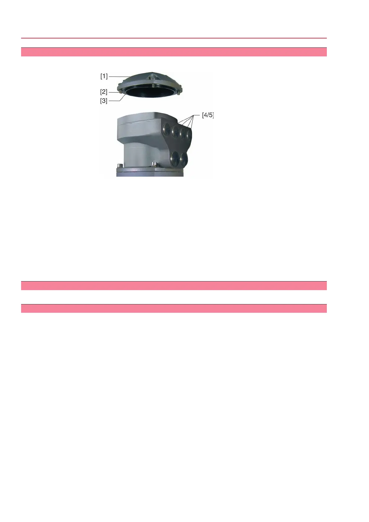
Figure 20: AUMA plug/socket connector SD bus
[1] Cover
[2] Screws for cover
[3] O-ring
[4] Cable entries for bus cables
[5] Blanking plug
1. Clean sealing faces of cover [1] and housing.
2. Apply a thin film of non-acidic grease (e.g. petroleum jelly) to the sealing faces.
3. Check whether O-ring [3] is in good condition, correctly insert O-ring.
4. Fit cover [1] and fasten screws [2] evenly crosswise.
5. Fasten cable glands with the specified torque to ensure the required enclosure
protection.
5.3 Accessories for electrical connection
– Option –
5.3.1 Controls mounted to wall bracket
The wall bracket allows separate mounting of controls and actuator.
Application
●
If the actuator cannot be accessed.
●
If the actuator is subject to high temperatures.
●
In case of heavy vibration of the valve.
24
SG 05.1 – SG 12.1/SGR 05.1 – SGR 12.1 Control unit: electromechanic
Electrical connection AC 01.1 Intrusive Modbus RTU
 Loading...


