9.10 Intermediate positions: set
— Option —
Actuators equipped with DUO limit switching contain two intermediate position
switches. One intermediate position may be set for each running direction.
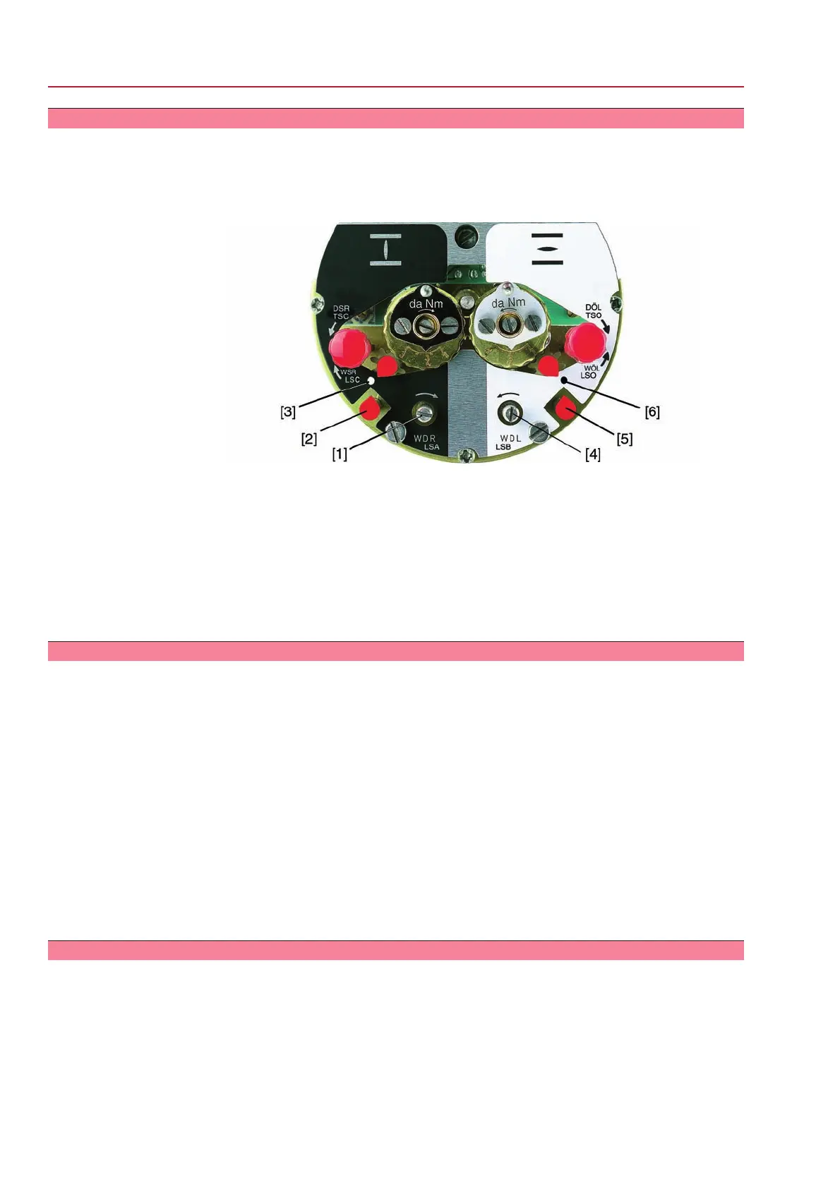
Figure 47: Setting elements for limit switching
Black section:
[1] Setting spindle: Running direction CLOSE
[2] Pointer: Running direction CLOSE
[3] Mark: Intermediate position CLOSED is set
White section:
[4] Setting spindle: Running direction OPEN
[5] Pointer: Running direction OPEN
[6] Mark: Intermediate position OPEN is set
9.10.1 Running direction CLOSE (black section): set
1. Move valve in direction CLOSE to desired intermediate position.
2. If you override the tripping point inadvertently: Turn valve in opposite direction
and approach intermediate position again in direction CLOSE.
Information: Always approach the intermediate position in the same direction
as in later electrical operation.
3. Press down and turn setting spindle [1] with screw driver in direction of the
arrow and observe the pointer [2]: While a ratchet click is felt and heard, the
pointer [2] moves 90° every time.
4. If the pointer [2] is 90° from mark [3]: Continue turning slowly.
5. If the pointer [2] moves to mark [3]: Stop turning and release setting spindle.
➥
The intermediate position setting in running direction CLOSE is complete.
6. If you override the tripping point inadvertently (ratchet click is heard after the
pointer has snapped): Continue turning the setting spindle in the same direction
and repeat setting process.
9.10.2 Running direction OPEN (white section): set
1. Move valve in direction OPEN to desired intermediate position.
2. If you override the tripping point inadvertently: Move valve in opposite direction
and approach intermediate position again in direction OPEN (always approach
the intermediate position in the same direction as in later electrical operation).
3. Press down and turn setting spindle [4] with screw driver in direction of the
arrow and observe the pointer [5]: While a ratchet click is felt and heard, the
pointer [5] moves 90° every time.
4. If the pointer [5] is 90° from mark [6]: Continue turning slowly.
50
SG 05.1 – SG 12.1/SGR 05.1 – SGR 12.1 Control unit: electromechanic
Commissioning (basic settings) AC 01.1 Intrusive Modbus RTU
 Loading...


