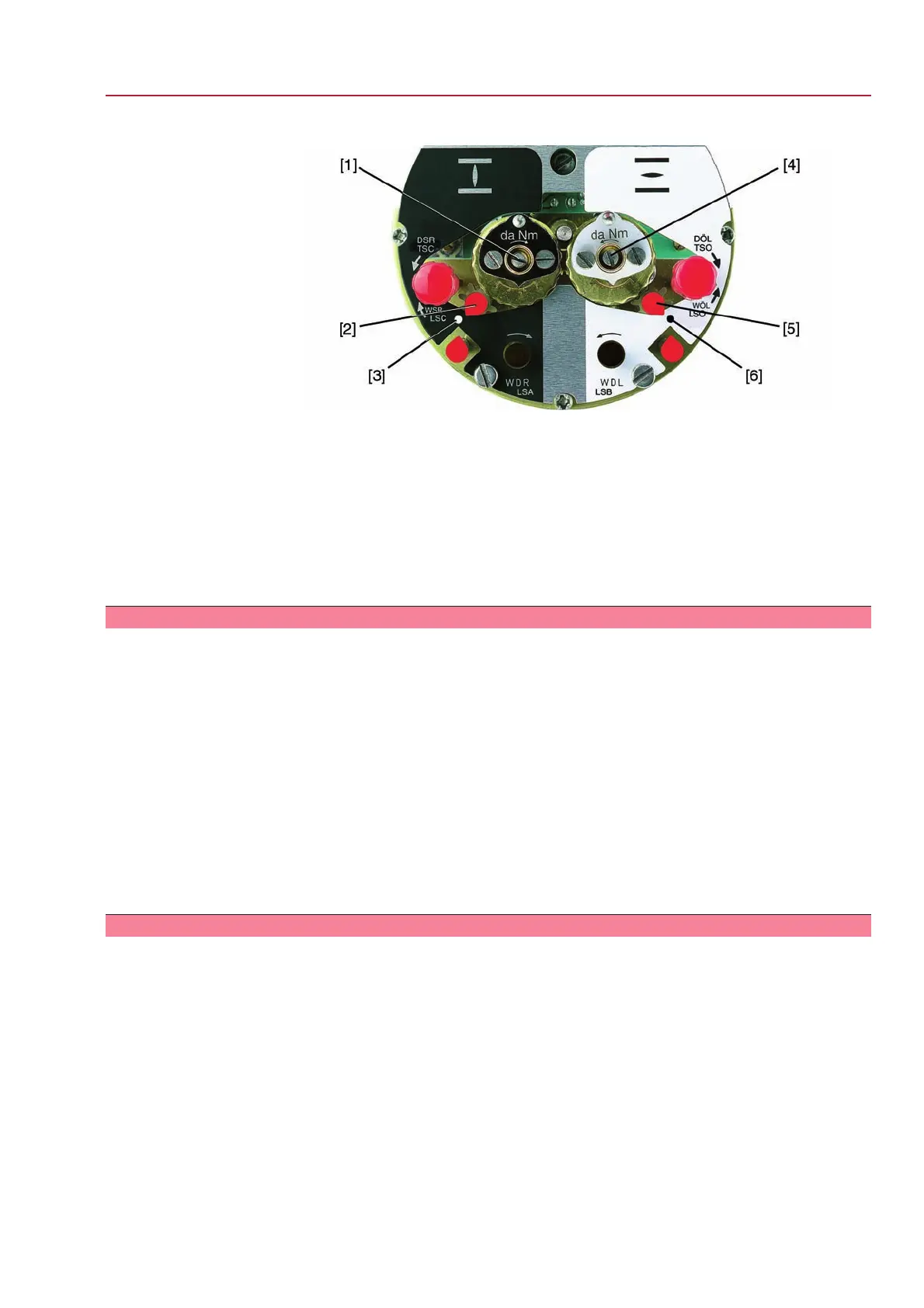
Figure 46: Setting elements for limit switching
Black section:
[1] Setting spindle: End position CLOSED
[2] Pointer: End position CLOSED
[3] Mark: End position CLOSED is set
White section:
[4] Setting spindle: End position OPEN
[5] Pointer: End position OPEN
[6] Mark: End position OPEN is set
9.9.1 End position CLOSED (black section): set
1. Engage manual operation.
2. Turn handwheel clockwise until valve is closed.
3. To prevent that the end stop is reached (due to overrun) before the limit switch
has tripped, turn handwheel 4 turns (overrun) in the opposite direction.
4. Press down and turn setting spindle [1] with screw driver in direction of the
arrow and observe the pointer [2]: While a ratchet click is felt and heard, the
pointer [2] moves 90° every time.
5. If the pointer [2] is 90° from mark [3]: Continue turning slowly.
6. If the pointer [2] moves to mark [3]: Stop turning and release setting spindle.
➥
The end position CLOSED setting is complete.
7. If you override the tripping point inadvertently (ratchet click is heard after the
pointer has snapped): Continue turning the setting spindle in the same direction
and repeat setting process.
9.9.2 End position OPEN (white section): set
1. Engage manual operation.
2. Turn handwheel counterclockwise until valve is open.
3. To prevent that the end stop is reached (due to overrun) before the limit switch
has tripped, turn handwheel 4 turns (overrun) in the opposite direction.
4. Press down and turn setting spindle [4] with screw driver in direction of the
arrow and observe the pointer [5]: While a ratchet click is felt and heard, the
pointer [5] moves 90° every time.
5. If the pointer [5] is 90° from mark [6]: Continue turning slowly.
6. If the pointer [5] moves to mark [6]: Stop turning and release setting spindle.
➥
The end position OPEN setting is complete.
7. If you override the tripping point inadvertently (ratchet click is heard after the
pointer has snapped): Continue turning the setting spindle in the same direction
and repeat setting process.
49
SG 05.1 – SG 12.1/SGR 05.1 – SGR 12.1 Control unit: electromechanic
AC 01.1 Intrusive Modbus RTU Commissioning (basic settings)
 Loading...


