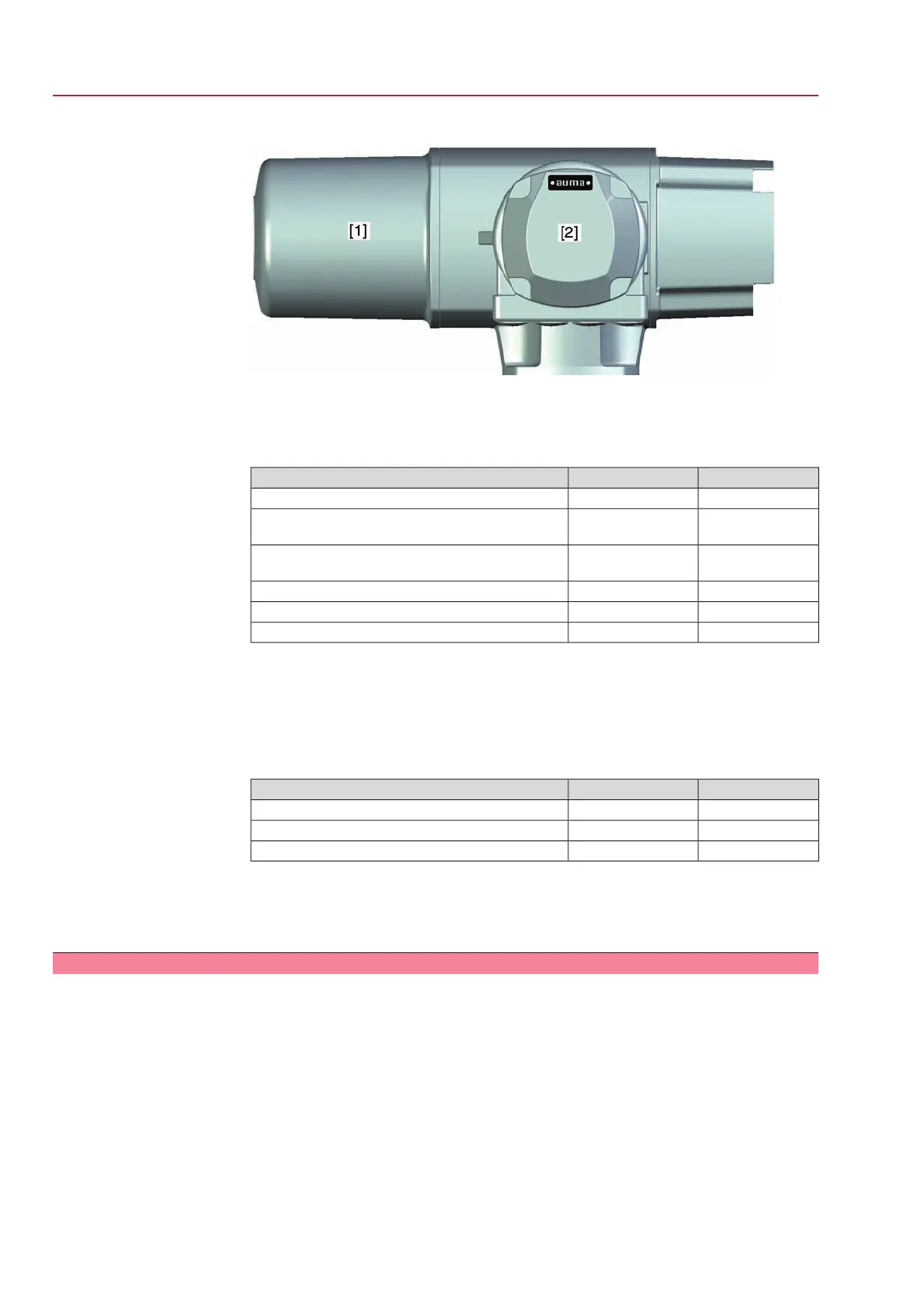
Figure 58: Access to fuses
[1] Rear cover
[2] Electrical connection
F1/F2
Primary fuses on power supply unit
AUMA Art. No.:F1/F2G fuses
6.3 x 32 mmSize
K002.2771 A T; 500 VReversing contactors
Power supply 싨 500 V
K002.6652 A FF; 660 VReversing contactors
Power supply > 500 V
K001.18516 A FF; 500 VThyristor units for motor power up to 1.5 kW
K006.96530 A FF; 500 VThyristor units for motor power up to 3.0 kW
K002.2771 A T; 500 VThyristor units for motor power up to 5.5 kW
F3
Internal 24 V DC supply
F4
Internal 24 V AC supply (115 V AC) for:
●
Heater, switch compartment, reversing contactors control
●
PTC tripping device
●
for 115 V AC also control inputs OPEN - STOP - CLOSE
F4F3G-fuse according to IEC 60127-2/III
5 x 20 mm5 x 20 mmSize
1.25 A T; 250 V1.0 A T; 250 VVoltage output (power supply unit) = 24 V
0.315 A T; 250 V1.0 A T; 250 VVoltage output (power supply unit) = 115 V
F5
Automatic reset fuse as short-circuit protection for external 24 V DC supply for
customer (see wiring diagram)
Information After fuse replacement, replace and fasten cover.
10.3.2 Motor protection (thermal monitoring)
In order to protect against overheating and impermissibly high temperatures at the
actuator, PTC thermistors or thermoswitches are embedded in the motor winding.
The thermoswitch is tripped as soon as the max. permissible winding temperature
has been reached.
The actuator is switched off and the following signals are given:
●
LED 3 (thermal fault) on the local controls is illuminated.
●
Status indication S0: Operation mode OFF/LOCAL = FLT + NR
●
Status indication S0/S6: Operation mode REMOTE = FAULT IND.
●
Status indication S1: THERMAL FAULT
The motor has to cool down before the operation can be resumed. Depending on
the parameter setting, the fault signal is either automatically reset or the fault signal
has to be acknowledged.
60
SG 05.1 – SG 12.1/SGR 05.1 – SGR 12.1 Control unit: electromechanic
Corrective action AC 01.1 Intrusive Modbus RTU
 Loading...


