2. Move valve to end position CLOSED.
3.
Turn lower indicator disc until symbol
(CLOSED) is in alignment with the
mark
on the cover.
4. Move actuator to end position OPEN.
5.
Hold lower indicator disc in position and turn upper disc with symbol
(OPEN)
until it is in alignment with the mark
on the cover.
6. Move valve to end position CLOSED again.
7. Check settings:
If the symbol
(CLOSED) is no longer in alignment with mark on the cover:
→
Repeat setting procedure.
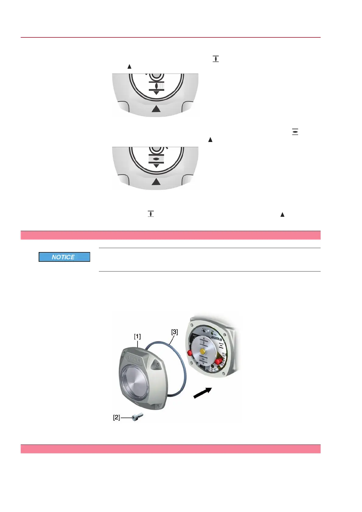
9.15 Switch compartment: close
Danger of corrosion due to damage to paint finish!
→
Touch up damage to paint finish after work on the device.
1. Clean sealing faces of housing and cover.
2. Check whether O-ring [3] is in good condition, replace if damaged.
3. Apply a thin film of non-acidic grease (e.g. petroleum jelly) to the O-ring and
insert it correctly.
4. Place cover [1] on switch compartment.
5. Fasten screws [2] evenly crosswise.
9.16 Operating time: set
For part-turn actuators with 1-phase AC motors the operating time can be adjusted.
54
SG 05.1 – SG 12.1/SGR 05.1 – SGR 12.1 Control unit: electromechanic
Commissioning (basic settings) AC 01.1 Intrusive Modbus RTU
 Loading...


