p 27/58
Technical Manual NAM-BL4x-MT-EN-C
The information in this document is the property of Automatic Systems and is confidential. The consignee withholds from using it for anything other than the use of the products or the execution of the
project to which they belong and withholds from communicating it to third parties without prior written agreement from Automatic Systems. Document subject to change without prior notice.
4. INSTALLATION
Installation must be undertaken in compliance with the safety warnings (Ch. 1. ).
4.1. Storing the equipment before installation
Before installation, ensure that the equipment does not get damaged, leave it in its original packaging, and
place it in a dry area protected from dust, heat and weather.
Store between -30 and +80°C [-22°F and 176°F].
4.2. Positioning the equipment
Since the barrier cannot be laid flush with the road surface, a perfectly horizontal raised concrete base must
be prepared, according to the installation drawing provided with the equipment.
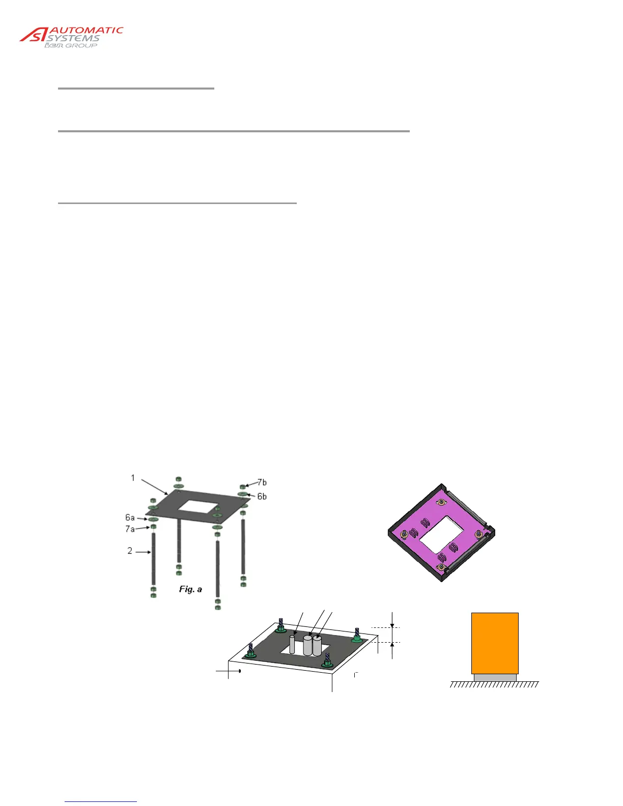
1. Assemble the fixing frame:
Pass the four anchoring bolts (2) into the holes of the fixing frame (1) using a nut (7a) and a flat washer
(6a) each time. The threaded must be installed as illustrated in Fig. a.
Secure the anchoring bolts on the fixing frame by putting a flat washer (6b) and a nut (7b) on each
threaded rod with a 40 mm [1,57 in] tail. Tighten the nuts. It is advisable to protect the threads sticking
out of the fixing frame from concrete projections by means of adhesive tape.
2. Provide 2 PVC tube (3 & 4) of minimum diameter 25.4mm [1 in]. One conduit for the power supply and
one for the remote control wires (Fig. b).
When appropriate, pass a PVC tube (5) of diameter 25 mm [1 in] to pass the optional detection loops
wires.
Ensure that the cables have a minimum of 1 metre [3.3 ft] out of the concrete base.
3. Construct a concrete base (8) in which the fixing frame is to be buried. The fixing frame must be flush
with the finished level of the concrete base and perfectly horizontal (Fig. b).
4. When the concrete is dry, remove the adhesive protection tape from the threads, remove the nuts (7b),
the flat washers (6b), put the barrier housing onto the concrete base and maintain it by means of the
washers (6b) and the nuts (7b) (Fig. c). The concrete base is designed smaller than the barrier
housing in order to prevent water stagnating at the bottom of the housing.
Fig. c
Fig. d
Fig. b
40 mm
3
5
8
4