p 40/58
Technical Manual NAM-BL4x-MT-EN-C
The information in this document is the property of Automatic Systems and is confidential. The consignee withholds from using it for anything other than the use of the products or the execution of the
project to which they belong and withholds from communicating it to third parties without prior written agreement from Automatic Systems. Document subject to change without prior notice.
4.7. Electrical connections
WARNING: do not connect to a floating network or to high impedance earthed industrial distribution network.
WARNING
: high leakage current.
Imperatively connect terminal block (21) to the ground before connecting the mains.
Do not connect several equipments to the same differential breaker.
The operations must be undertaken in accordance with the safety warnings, Ch. 1.
Connections must be executed in accordance with the wiring diagrams provided inside the equipment, which
remain the reference.
In order to avoid interference, power and control cables must be placed in two different conduits separated by
at least 10 cm.
The arm must be mounted before proceeding to electrical connections!
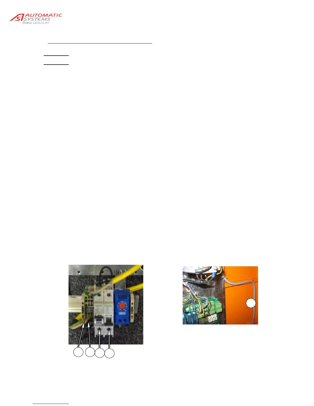
Turn off the circuit breaker (20) (► OFF). If there is a heater also turn off the heater breaker
(24).
Connect the power supply neutral wire to the terminal block (23) and the live wire to the main breaker
(20), making sure their properties comply with required specifications (Ch. 7. ).
Upstream of the power supply provide:
- Either a 15A/300mA leakage breaker (max. 5 barriers).
- Or a 15A/30mA leakage breaker of the selective Super Immunised type (max. 1 barrier).
Connect the various control units and possible options in compliance with the diagram
supplied, avoiding the power cable (22).
Connect the ground wires to their terminals:
- Cable between the housing and the cover
(check this connection each time the cover is closed)
- Cable between the housing and the doors
(check this connection each time the door is closed)
- Ground cable from power supply (21).
- Tranfo ground
- Logic ground
Test the proper operation of the equipment: see Ch. 6.1.
22
20
2321
24